
EMS Builder Architecture, Operating Modes, and Capability Boundaries
Edge-EMS Builder sits between field devices and higher-level systems. It is built around autonomous edge operation and can expand to cloud-edge and multinode coordination, organizing data reads, state calculations, rule evaluation, and action execution into a continuously running control loop.
This article answers four questions:
- How is Edge-EMS Builder’s architecture layered?
- Which operating modes does it support?
- How are business requirements assembled from its capabilities?
- How far can wired, wireless, and intersite connections extend?
“Operating modes” here refers to system operation, not commercial engagement. For the Platform, Solution, and Co-create engagement models, see Edge-EMS Builder service models.
1. Overall architecture: a loop across the field, edge, and cloud
Section titled “1. Overall architecture: a loop across the field, edge, and cloud”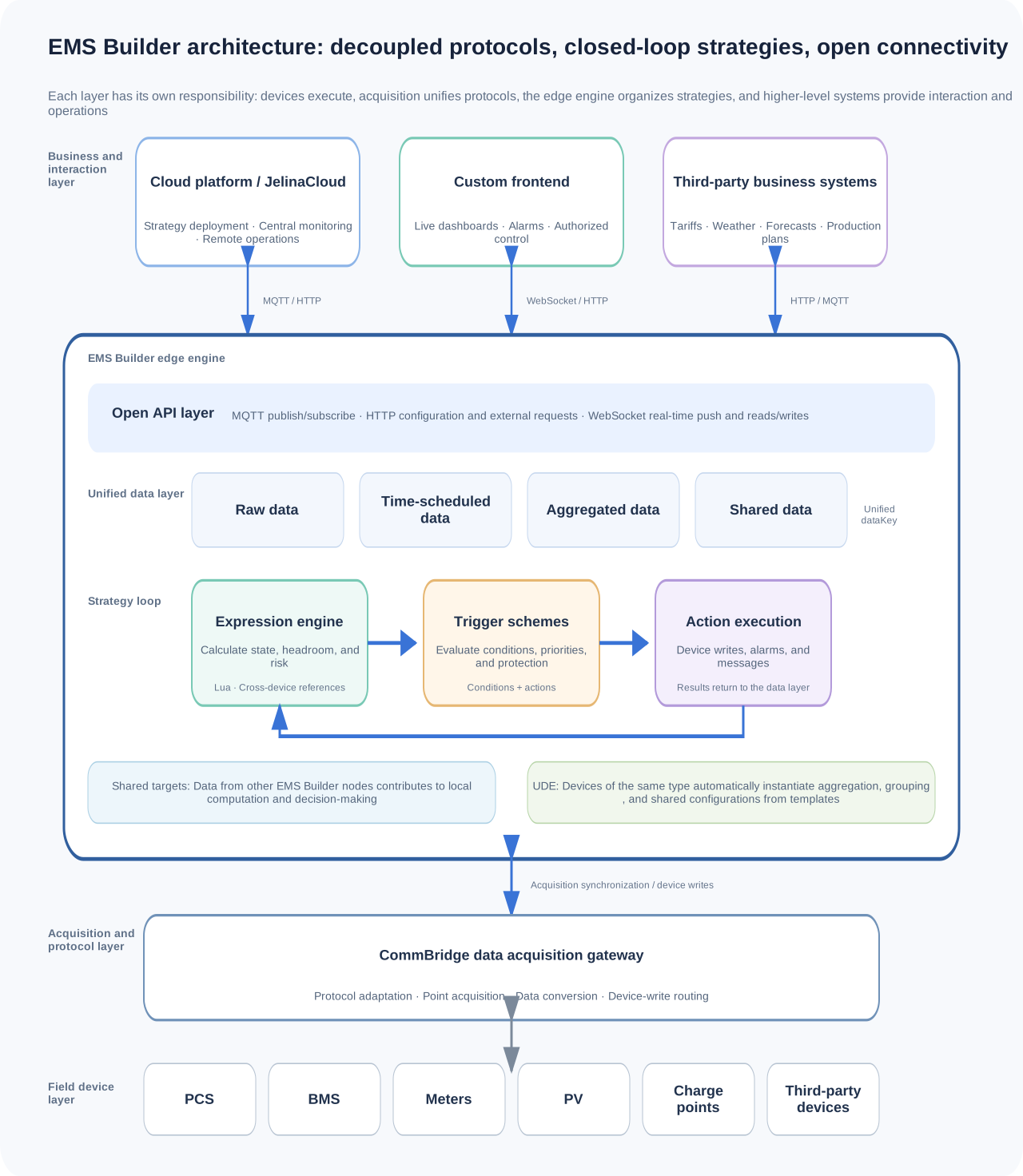
Edge-EMS Builder runs at the edge. CommBridge abstracts field-protocol differences, while MQTT, WebSocket, and HTTP connect clouds, frontends, and third-party systems.
| Layer | Core responsibilities | Typical objects / channels |
|---|---|---|
| Business and cloud layer | Centralized monitoring, remote configuration, strategy deployment, operational analysis, and third-party business integration | JelinaCloud, customer cloud platforms, SCADA, dispatch systems; MQTT / HTTP |
| Interaction and integration layer | Push real-time data to frontends, receive control commands, and provide external systems with read/write capabilities | Custom web frontends, backend services; WebSocket / HTTP |
| EMS Builder edge engine | Unified data, real-time calculations, strategy evaluation, action execution, alarms, sharing, and configuration expansion | Data model, expression engine, trigger schemes, shared targets, UDE |
| CommBridge acquisition layer | Adapt underlying protocols and convert field points into data EMS Builder recognizes | Modbus, OPC UA, S7, serial, IEC 101/104, CAN, etc. |
| Field device layer | Supply real-time data and perform final control actions | PCS, BMS, meters, charge points, PV inverters, sensors, third-party devices |
Why use layers
Section titled “Why use layers”- Device changes do not force strategy rewrites: the acquisition layer adapts protocols and points; higher-level strategies use a unified
dataKey. - Business changes do not alter communication drivers: thresholds, time periods, and control rules change in the strategy layer without modifying protocol implementations.
- Interfaces are decoupled from the control engine: Edge-EMS Builder has no fixed UI; frontends subscribe to data and initiate control through standard channels.
- Local loops can continue when the cloud is unavailable: critical decisions and actions run at the edge. Specific offline capabilities depend on project configuration and external dependencies.
2. How a control action is completed
Section titled “2. How a control action is completed”Any business strategy can be divided into four steps: acquisition → calculation → decision → execution.
| Step | What EMS Builder does | Example: distribution-area capacity support |
|---|---|---|
| ① Acquisition | CommBridge reads raw points and synchronizes them to EMS Builder | Read transformer load, PCS status, and SOC |
| ② Calculation | The expression engine computes intermediate states, headroom, or risks | Calculate capacity shortfall and available storage discharge power |
| ③ Decision | Trigger schemes evaluate conditions and select actions | Start support when load approaches the limit and SOC permits |
| ④ Execution | Write devices, record alarms, publish MQTT, or push to frontends | Send power commands to PCS and report execution status |
Power, SOC, and device status after execution are acquired again for the next evaluation cycle. A stable strategy also needs start/exit thresholds, debouncing, priorities, communication exception handling, device protection, and manual takeover, beyond a simple IF / THEN.
Two mechanisms supporting the entire loop
Section titled “Two mechanisms supporting the entire loop”- Shared targets: data from other Edge-EMS Builder nodes participates in expressions and trigger evaluation like local data, enabling cross-device coordination.
- Unit Dynamic Expansion (UDE): define one template for similar devices; new instances automatically materialize aggregation, group, and sharing configuration, reducing repetitive setup.
3. Three operating modes
Section titled “3. Three operating modes”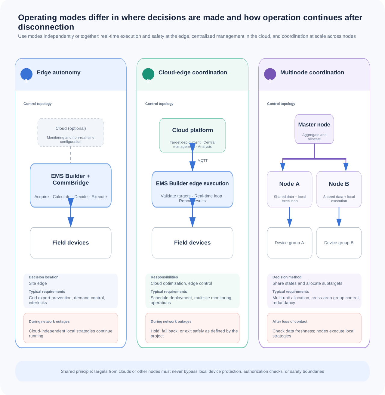
All three modes use the same Edge-EMS Builder engine and can operate independently or together within a project.
1. Edge autonomy
Section titled “1. Edge autonomy”Data acquisition, calculation, evaluation, and control all take place within the site. This suits scenarios with demanding response-time, continuous-operation, and data-localization requirements.
Typical flow: field devices → CommBridge → Edge-EMS Builder strategies → field devices
Suitable requirements: time-scheduled charging/discharging, grid export prevention, demand control, device interlocks, and site alarms.
Design focus: local protection takes priority. Provide caching, timeouts, and fallback behavior for dependencies such as external tariffs, weather, or cloud commands.
2. Cloud-edge coordination
Section titled “2. Cloud-edge coordination”The edge performs real-time execution; the cloud handles centralized management, strategy orchestration, remote operations, or cross-site analysis. MQTT supports bidirectional publish/subscribe and response mechanisms. Edge-EMS Builder can also retrieve authorized external information through HTTP.
Typical flow: cloud sends targets/strategies → edge validates and executes → results return to cloud
Suitable requirements: multisite monitoring, remote parameter adjustments, scheduled profile deployment, operational analysis, and centralized alarms.
Design focus: cloud targets cannot bypass site safety boundaries. Define whether a network outage means continuing execution, holding the last valid value, or entering a safe strategy.
3. Multinode coordination
Section titled “3. Multinode coordination”Multiple Edge-EMS Builder devices synchronize data through shared targets. A master node can aggregate slave-node states and perform centralized calculations; slave nodes can take on new tasks after role changes.
Typical flow: multiple slave nodes share data → master calculates site targets → nodes execute allocated targets
Suitable requirements: multi-unit power allocation, device-group control across areas, site-level load balancing, redundancy, and role switching.
Design focus: define master/slave relationships, sharing intervals, data freshness, network fault states, and local strategies after loss of contact.
4. Core capabilities and operational support
Section titled “4. Core capabilities and operational support”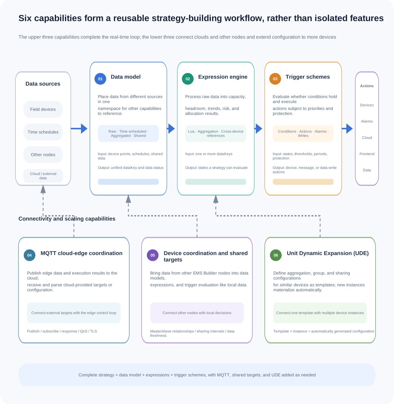
| Capability | Problem addressed | Role in the loop |
|---|---|---|
| Data model | Unifies the organization of raw, time-scheduled, aggregated, and shared data | Foundation for acquisition and calculation |
| Expression engine | Uses Lua for summation, filtering, state evaluation, and cross-device computation | Calculation |
| Trigger schemes | Orchestrates business rules using conditions + actions | Decision and execution |
| MQTT cloud-edge coordination | Data publishing, command subscriptions, responses, and bidirectional cloud-edge communication | Cloud-edge connectivity |
| Device coordination and shared targets | Allows multiple nodes to share data and participate in each other’s calculations | Distributed coordination |
| Unit Dynamic Expansion (UDE) | Templates, dynamic placeholders, and reconciliation of existing instances | Scaling |
| Alarm lifecycle | Tracks abnormalities, recovery, and manual resolution | Status and handling |
| History and archiving | Trend analysis, asynchronous export, and multiple archive plans | Data retention |
| Operations and maintenance | Capacity recommendations, configuration sources, maintenance freeze, and control logs | Continuous operation |
Real-time frontend push and direct control also provides WebSocket channels for frontends and backend systems, allowing custom interfaces to subscribe to real-time data and initiate control within permission and safety constraints.
5. Combining capabilities for different requirements
Section titled “5. Combining capabilities for different requirements”Edge-EMS Builder does not prescribe one strategy for every project. It supports different requirements through the same construction method:
Requirement = required data + calculation rules + trigger conditions + execution actions + protection and validation
| Requirement | Required data | Calculations and evaluation | Typical actions |
|---|---|---|---|
| Peak shaving and valley filling / demand control | Grid connection power, SOC, PCS status, demand target | Calculate power shortfall and available charging/discharging capability | Send PCS power commands and record strategy state |
| Grid export prevention | Grid connection power, PV power, available storage power | Detect export trends and limit output | Absorb power into storage, curtail PV, or raise alarms |
| Charging load balancing | Transformer headroom, charge-point demands and status | Calculate available power and allocate it according to rules | Adjust each charge point’s power limit |
| Multi-unit coordination | Each unit’s SOC, power limit, and availability | Allocate site targets by SOC, capacity, or priority | Send subtargets to multiple PCS units/nodes |
| Time schedules and planned profiles | Time periods, tariffs, SOC, load forecasts | Match the current period and check protection boundaries | Switch charging/discharging targets and return execution results |
| External-information-driven control | Tariffs, weather, production plans, forecasts | Validate freshness and use data for optimization or evaluation | Adjust targets, enter fallback strategies, or raise alarms |
Example: translate a business statement into EMS Builder configuration
Section titled “Example: translate a business statement into EMS Builder configuration”The requirement is:
“When power at the grid connection point exceeds 800 kW, automatically discharge storage if SOC is above 20%; exit when power falls to 760 kW.”
Implementation needs at least:
- Grid connection power, SOC, PCS availability, maximum discharge power, and other data.
- Expressions for capacity shortfall and target discharge power.
- Dual thresholds: start at 800 kW and exit at 760 kW.
- PCS power-write actions, rate limits, and failure handling.
- SOC/temperature/alarm protection, manual takeover, and communication fault strategies.
- Test cases for normal, boundary, network-outage, and device-failure conditions.
Edge-EMS Builder thus provides the infrastructure for expressing and executing strategies. Their safety and correctness still depend on requirement definition, device capabilities, and validation quality.
6. Possibilities for wired, wireless, and intersite connectivity
Section titled “6. Possibilities for wired, wireless, and intersite connectivity”Edge-EMS Builder’s core logic is decoupled from the network medium. Network connectivity, however, does not mean every wireless link is suitable for real-time control.
Higher-level IP networks
Section titled “Higher-level IP networks”MQTT/MQTTS, HTTP, and WebSocket can operate over reachable IP networks. Projects can use Ethernet, Wi-Fi, 4G/5G, or private networks to connect clouds and other nodes, according to hardware and network conditions.
This is architectural feasibility, not a specification promising built-in wireless modules in Edge-EMS Builder edge hardware. Confirm wireless capabilities against the selected hardware, carrier network, site coverage, and certification requirements.
Field device networks
Section titled “Field device networks”Whether PCS, BMS, meters, and other devices can connect wirelessly depends on the devices, wireless gateways, and CommBridge protocol adaptation. Wireless is a transport medium; it does not automatically solve register mapping, real-time performance, or control-permission issues.
Additional considerations for wireless or wide-area connections
Section titled “Additional considerations for wireless or wide-area connections”- Latency and jitter: keep millisecond-level loops local; wide-area links are better suited to target delivery, data reporting, and coordination without hard real-time requirements.
- Disconnections and stale data: mark shared-data freshness and define hold, fallback, or exit behavior after disconnection.
- Security: use TLS, authentication, least privilege, and auditing. Avoid exposing device control interfaces directly to the public internet.
- Site protection: hardware interlocks, device protection, and local safety control must not depend on the cloud or unstable links.
The recommended overall principle is:
Keep real-time control at the edge; optimization targets may come from the cloud. Wireless provides connectivity, while safety and disaster recovery provide safeguards.
7. From wireless connectivity to broader expansion
Section titled “7. From wireless connectivity to broader expansion”Three conditions define the potential scope of Edge-EMS Builder:
| Prerequisite | Question to answer |
|---|---|
| Data is obtainable | Can required states be acquired reliably, from trustworthy and timely sources? |
| Rules are expressible | Can objectives, constraints, priorities, and exception paths be described and tested clearly? |
| Actions are executable | Do devices or systems offer compliant, authorizable, and verifiable control interfaces? |
When all three hold, Edge-EMS Builder can extend beyond traditional EMS into campus device-group control, flexible-load regulation, production-plan coordination, and environmental/energy coordination: automation scenarios following perception → decision → execution.
The following boundaries always remain:
- Edge-EMS Builder cannot replace manufacturers’ protective logic, safety certification, or site interlocks.
- External forecasts or AI results require range checks, timeouts, and safety limits. They must not bypass deterministic rules to control critical devices directly.
- Multidevice coordination depends on clocks, networks, data quality, and target-allocation algorithms.
- New strategies must be validated in simulation or test environments before entering production through controlled procedures.
8. Deployment capacity: start from measured results
Section titled “8. Deployment capacity: start from measured results”The currently validated recommended AFE-E630 scenario S3.5 uses a configured acquisition load of 5,000 points/second, 30 aggregations, 90 Trigger tasks/second, 20 MQTT tasks/second, and 10 coordination tasks/second, with change-based storage and a maximum save interval of 10 seconds.
In the 2026-07-29 test batch (report v1.3), this scenario achieved Trigger / MQTT P95 latency of 56 ms / 77 ms, whole-device CPU P95 of 71.09%, and whole-device actual memory P95 of 41.41%. For initial production capacity planning, reserve approximately 20% engineering headroom below this measured load.
These results use specified hardware/software and 2,000 valid short-term samples. They do not establish 72-hour stability and cannot be extrapolated directly to different scripts, message sizes, or database volumes. See the AFE-E630 performance test report.
Pre-deployment checklist
Section titled “Pre-deployment checklist”- Confirm device point lists, dimensions, precision, read/write permissions, and invalid values.
- Define strategy entry, exit, debouncing, priority, and conflict handling.
- Provide fallback paths for network loss, stale data, offline devices, and write failures.
- Ensure independent device protection, hardware interlocks, manual takeover, and permission auditing.
- Stress-test with real scripts, message sizes, historical database volumes, and target hardware.
- Establish configuration versions, rollback plans, and log/alarm monitoring.
Next steps
Section titled “Next steps”- Start with product value and scenarios: Edge-EMS Builder introduction.
- Understand configuration objects: Core concepts.
- Explore business configuration workflows: Temporary capacity support or Charging cluster load balancing.
- Review frontend and cloud integration: Real-time frontend push and direct control, MQTT cloud-edge coordination.