
Example: Temporary Distribution-Area Capacity Support
This example demonstrates that Edge-EMS Builder does not itself embed the business logic for capacity support. The strategy is assembled from three basic capabilities: acquisition, aggregation expressions, and trigger schemes. The same approach can configure any scenario following threshold monitoring → headroom calculation → action execution.
1. Business background
Section titled “1. Business background”A distribution transformer service area has fixed capacity, such as 315kVA or 400kVA. Brief concentrated loads, such as simultaneous vehicle fast charging or seasonal peaks, may approach or exceed the transformer’s rated capacity. Traditionally, an upgrade is requested from the utility, involving long lead times and high costs, often merely to handle short peaks.
Temporary capacity support deploys energy storage on the distribution-area side. Edge-EMS Builder monitors load in real time and commands storage discharge before load approaches the transformer capacity limit. Storage supplies part of the shortfall, keeping total grid import within a safe threshold. When load falls, the system automatically exits support mode and returns storage to normal dispatch, such as off-peak charging. Software strategies and storage equipment provide temporary capacity support without transformer modification.
2. Devices and data involved
Section titled “2. Devices and data involved”| Role | Device | Key points |
|---|---|---|
| Distribution-area main meter | Smart meter at the distribution transformer outgoing feeder | Total grid import power Feeder_active_power (kW) |
| Energy storage system | PCS + BMS | Current output PCS1_active_power (kW, positive for discharge), SOC PCS1_soc (%), discharge limit PCS1_max_discharge_power (kW) |
| Strategy parameters | Custom/aggregation points | Transformer rated capacity Transformer_rated_capacity (kW), capacity-support trigger ratio, SOC protection minimum |
These points come from the data model’s raw data (meter and PCS/BMS measurements) and time-scheduled/custom data (threshold parameters that operators can adjust seasonally without editing scripts).
3. Aggregation: remaining capacity and support requirement
Section titled “3. Aggregation: remaining capacity and support requirement”Create aggregation point Feeder_headroom_kw for remaining distribution-area capacity with this expression:
-- Remaining capacity = rated capacity × trigger ratio - measured grid import powerlocal rated = tonumber(${Transformer_rated_capacity} or 0)local ratio = tonumber(${Capacity_trigger_ratio} or 0.9)  -- Default trigger threshold: 90% of rated capacitylocal used = tonumber(${Feeder_active_power} or 0)
return rated * ratio - used
A negative Feeder_headroom_kw means load is approaching or exceeding the trigger threshold and storage must help carry the load.
4. Trigger scheme: discharge automatically as load approaches the threshold
Section titled “4. Trigger scheme: discharge automatically as load approaches the threshold”Trigger condition (data-change trigger, DATA_CHANGE):
return tonumber(${Feeder_headroom_kw} or 0) < 0Trigger action:
local resultList = {}
local headroom = tonumber(${Feeder_headroom_kw} or 0)   -- Negative value representing the power shortfalllocal soc = tonumber(${PCS1_soc} or 0)local maxDischarge = tonumber(${PCS1_max_discharge_power} or 0)
-- SOC protection: below the minimum, raise an alarm without capacity support to avoid overdischargeif soc < tonumber(${SOC_protect_min} or 20) then    table.insert(resultList, buildCommonAlarmMap(        "增容能力不足", "台区负荷超限但储能SOC过低(" .. soc .. "%),无法执行临时增容,请人工介入"    ))    return resultListend
-- Compensation power = absolute shortfall, capped by maximum storage discharge capabilitylocal needPower = math.min(-headroom, maxDischarge)
table.insert(resultList, buildCommonWriteMap("Collection", "PCS1_power_setpoint", needPower, nil, nil, true))table.insert(resultList, buildCommonAlarmMap("台区临时增容已启动", "台区负荷超限,储能按 " .. needPower .. " kW 放电分担负荷"))table.insert(resultList, buildMqttAlarmMap("台区临时增容已启动", "储能放电分担台区负荷", 1, "alarm/upload", 1))
return resultList
5. Exit condition: hysteresis to prevent frequent switching
Section titled “5. Exit condition: hysteresis to prevent frequent switching”Exiting whenever remaining capacity is ≥ 0 can repeatedly start and stop storage as load fluctuates near the threshold, commonly called oscillation. Introduce a hysteresis band: the entry and exit thresholds differ.
Create aggregation point Feeder_headroom_exit_kw for exit headroom, with a more conservative threshold ratio, such as 0.8 instead of 0.9:
local rated = tonumber(${Transformer_rated_capacity} or 0)local exitRatio = tonumber(${Capacity_exit_ratio} or 0.8)local used = tonumber(${Feeder_active_power} or 0)
return rated * exitRatio - used
Create another trigger scheme with conditions ${Feeder_headroom_exit_kw} >= 0 and ${PCS1_power_setpoint} > 0 (support mode is active). Its action gradually brings PCS1_power_setpoint to zero, exits support mode, and returns to normal dispatch, such as off-peak charging.
6. Combining other capabilities
Section titled “6. Combining other capabilities”- Multiple storage systems: use Device coordination to combine available capacity from multiple systems into one aggregation point. In trigger actions, allocate discharge tasks by SOC or rated-power ratio, following the equal-allocation approach in Charging load balancing.
- Cloud visualization and dispatch: use Cloud-edge coordination to periodically report
Feeder_headroom_kw, support start/stop status, storage output, and other information. Operators can remotely monitor multiple distribution areas, while the cloud can send threshold parameters to adjust strategies dynamically. - Reuse at scale: for many similarly structured distribution areas in a project batch, with the same PCS/BMS models and strategy framework, use Unit Dynamic Expansion to define these aggregation points as templates. New areas automatically generate configuration without rebuilding each one.
7. Summary
Section titled “7. Summary”Every capability used here—raw acquisition, aggregation expressions for headroom, data-condition triggers, write commands, alarms, and MQTT reporting—is a generic Edge-EMS Builder component. The specific temporary-capacity-support logic is assembled entirely through configuration. Replace the meter and PCS with other devices and thresholds with other business rules, and the same approach applies to peak shaving and valley filling, demand control, complementary energy-source coordination, and almost any monitoring → decision → execution scenario.
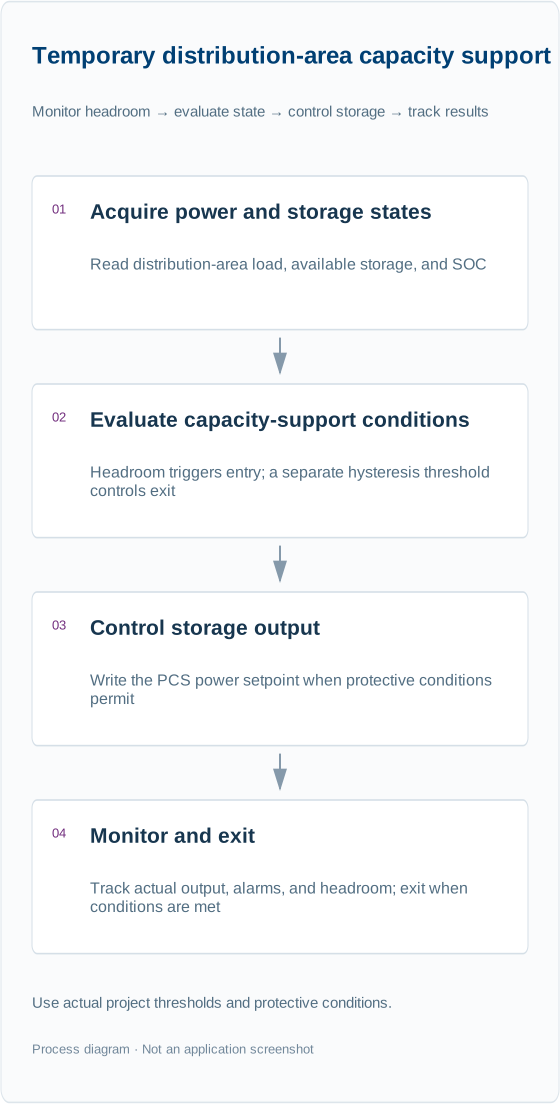
This diagram follows the configuration logic on this page and illustrates data and control flow. Refer to the configuration descriptions and scripts for specific fields.
⚠️ Threshold ratios, minimum SOC protection, and other parameters are examples only. Actual projects must account for transformer ratings, available storage capacity, local dispatch requirements, and other relevant factors.