
Serial communication acquisition
Reads and writes local serial ports using specified communication formats.
1. Create nodes
Section titled “1. Create nodes”(1) Open CommBridge Digital Twin and switch to Device Connectivity.
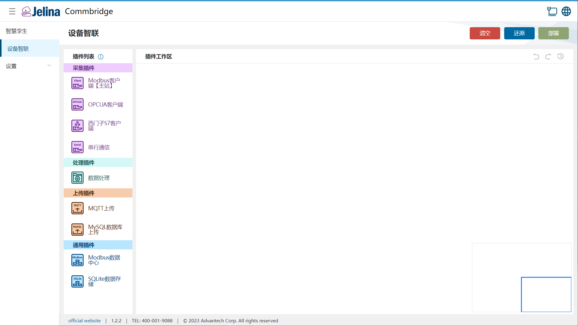
(2) Drag Serial Communication, Data Processing, and MQTT Upload into the workspace to create three nodes.

(3) Connect Serial Communication → Data Processing → MQTT Upload.

2. Create a scheme
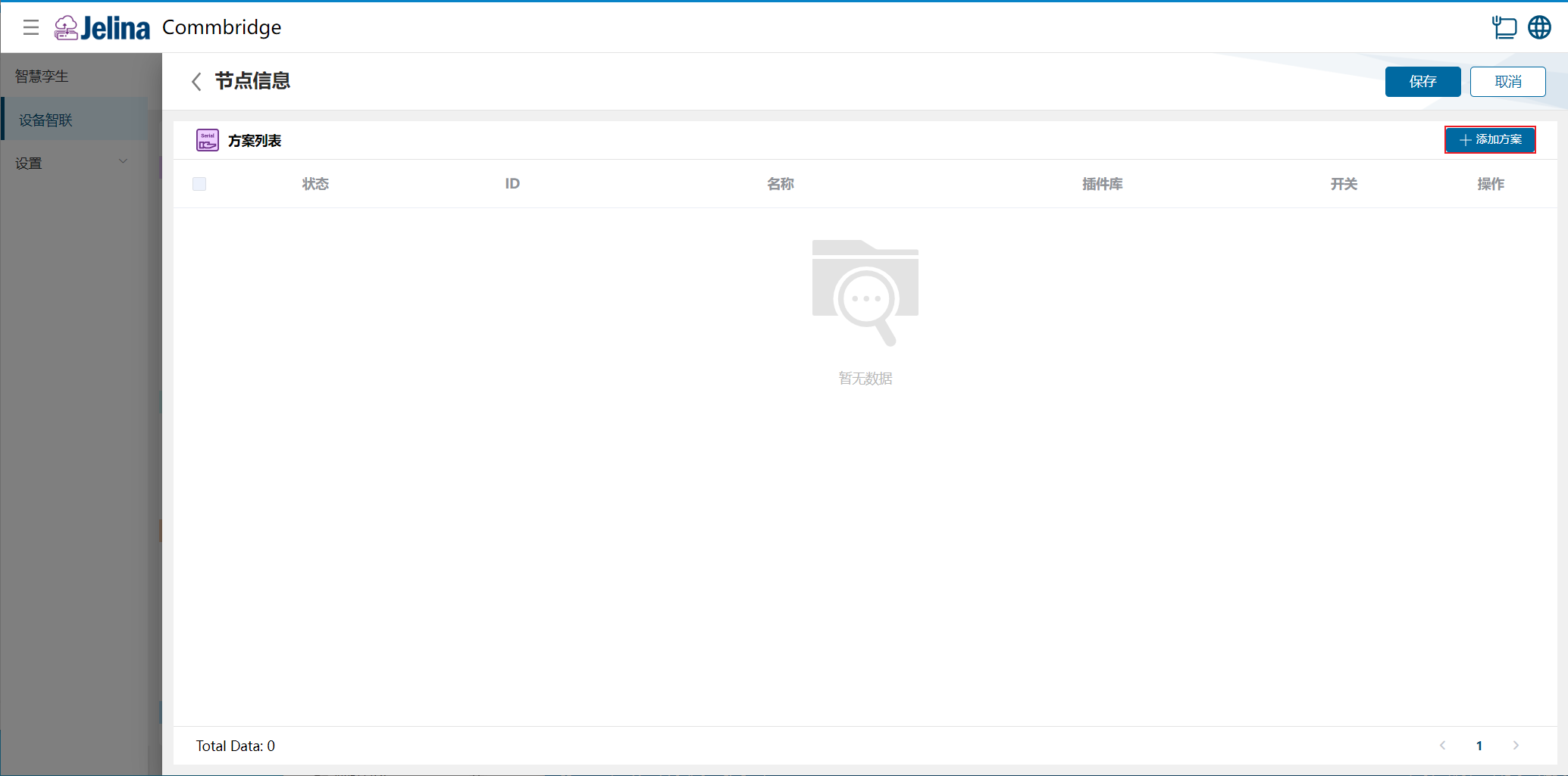
Section titled “2. Create a scheme”(1) Double-click Serial Communication and select Add scheme.
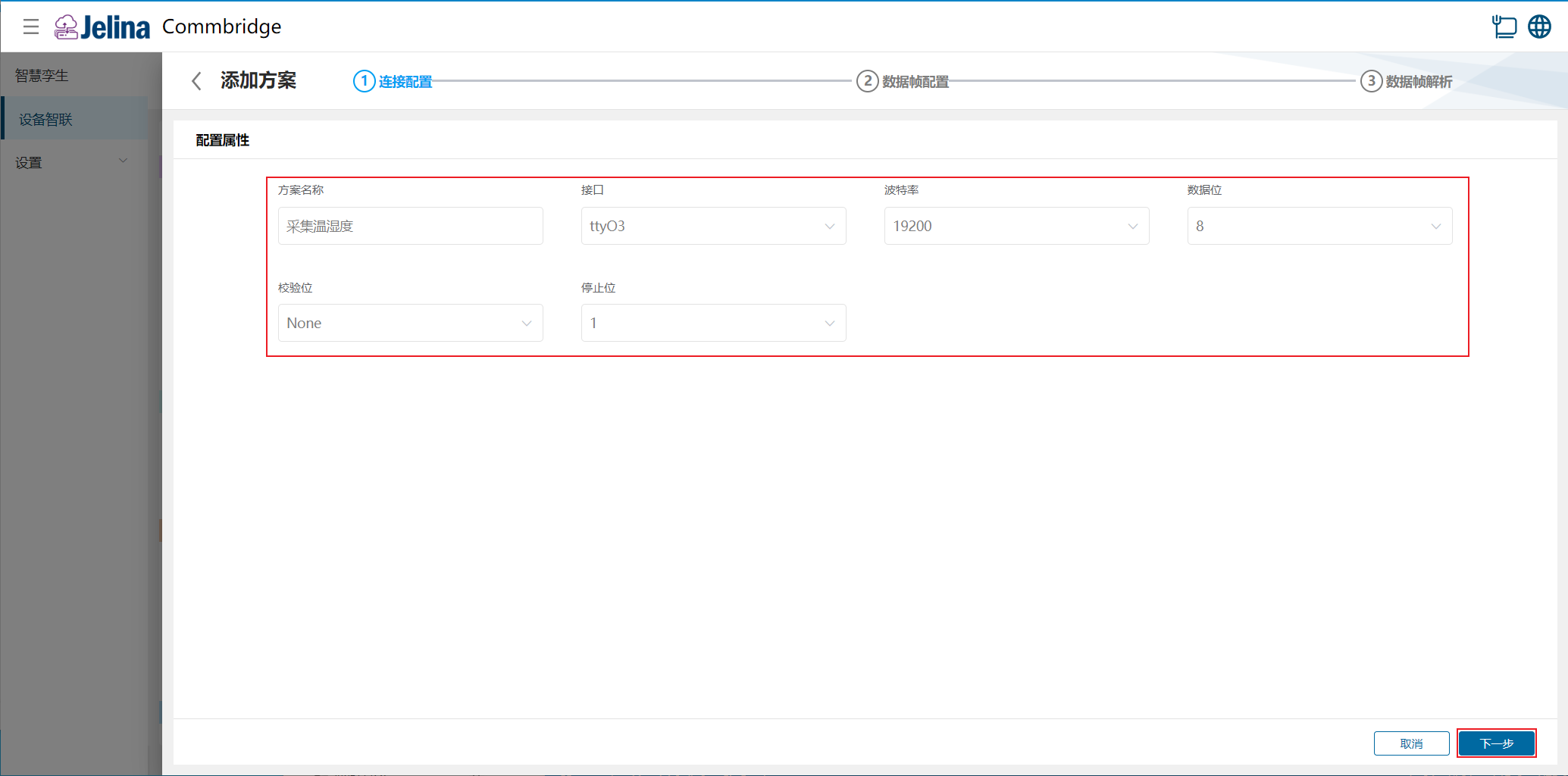
(2) Enter connection settings and select Next.
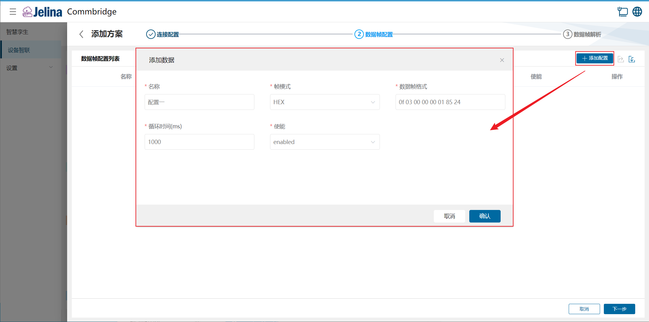
(3) Select Add configuration, enter the settings, and confirm.
(4) Select Next to open data frame parsing.
(5) Select Add parser, enter point configuration, and confirm.
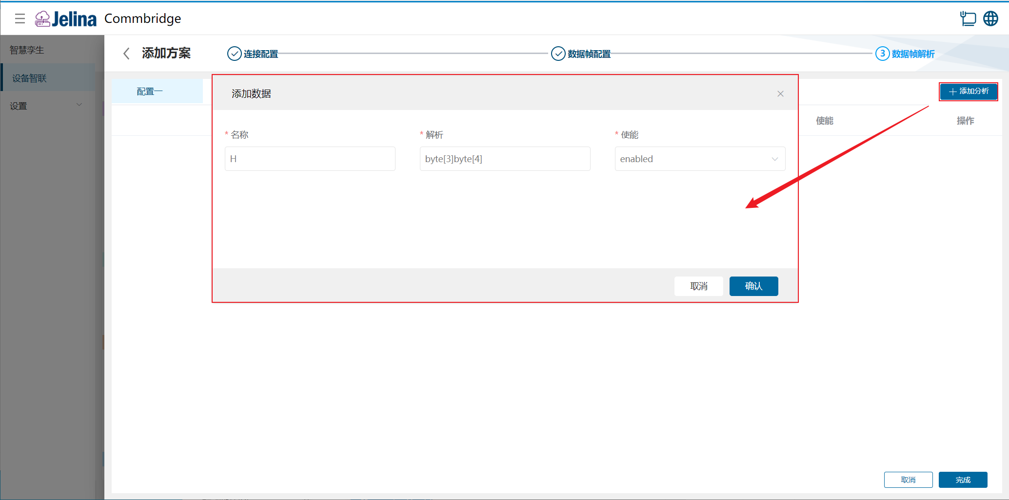
(6) Select Finish to add the acquisition scheme.
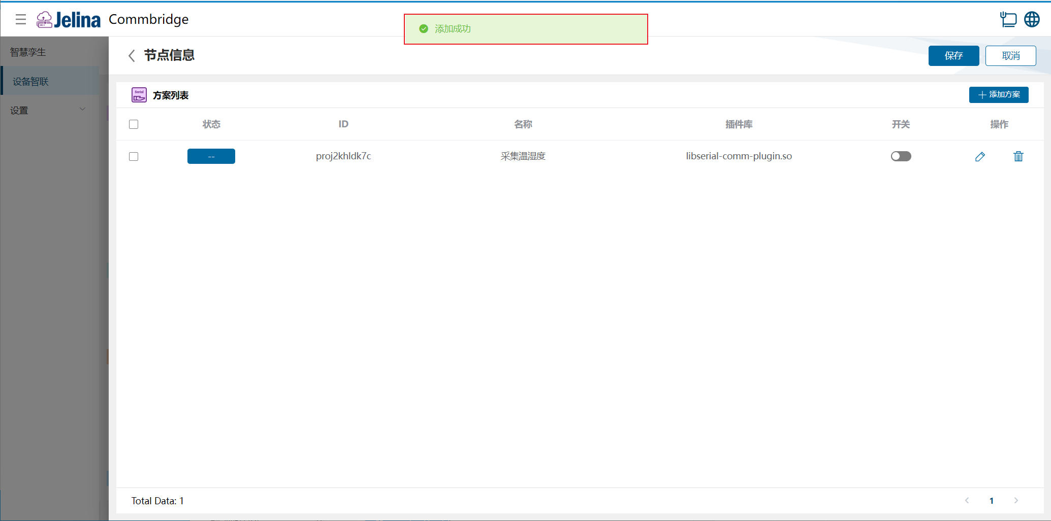
(7) Enable the scheme and select Save.
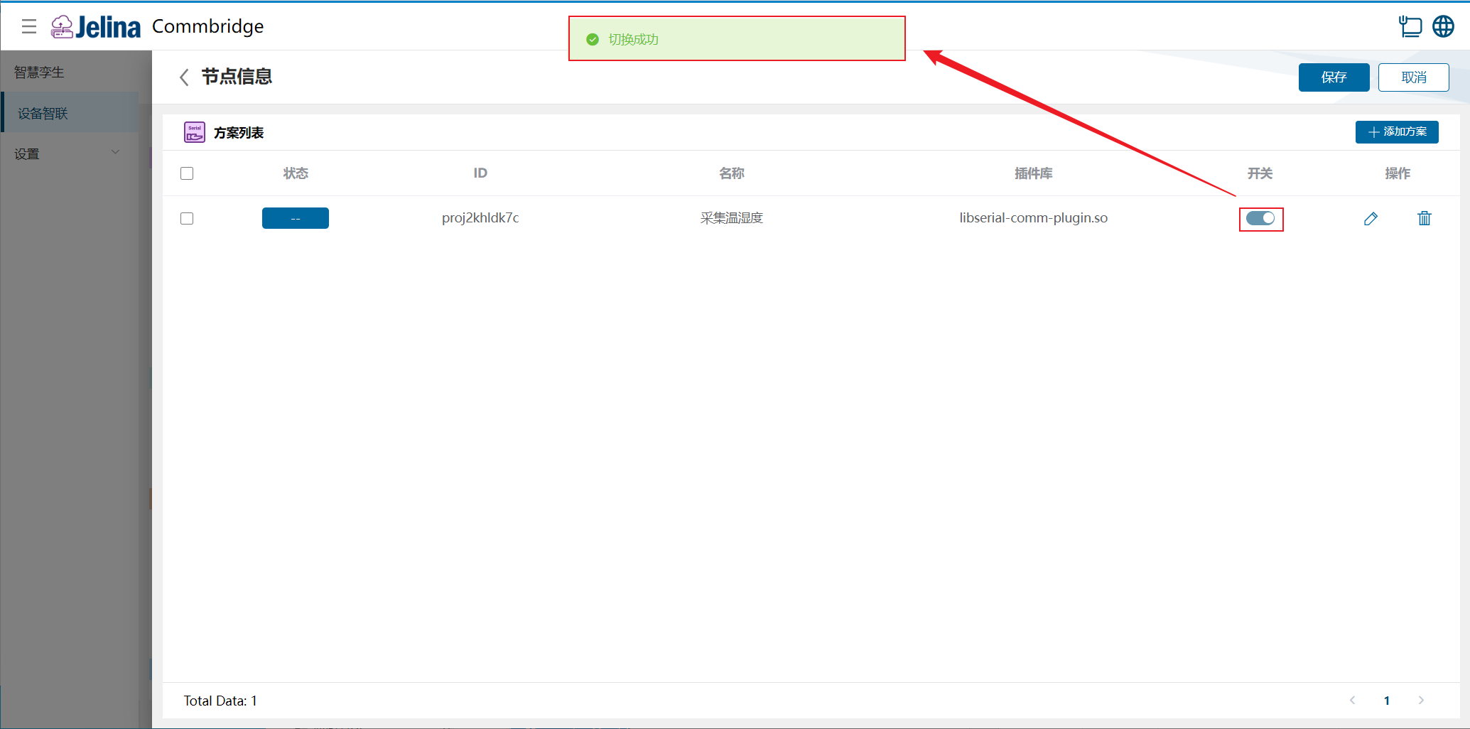
3. View results
Section titled “3. View results”(1) Select Deploy under Device Connectivity and wait for success.
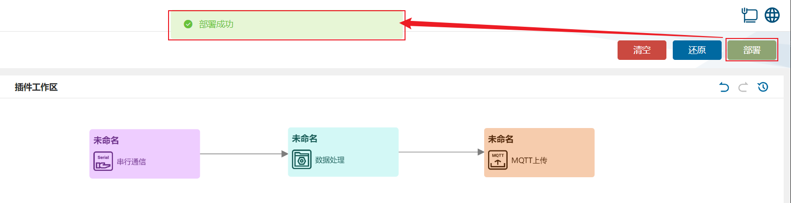
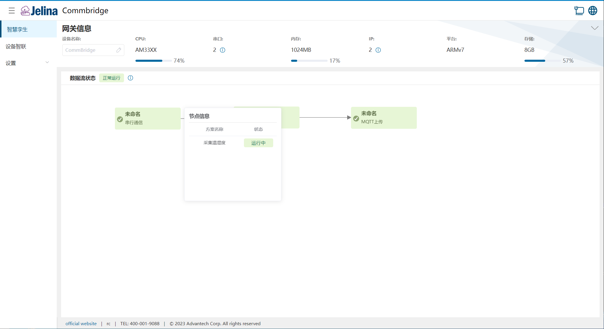
(2) Switch to Digital Twin and hover over Serial Communication to display node information.
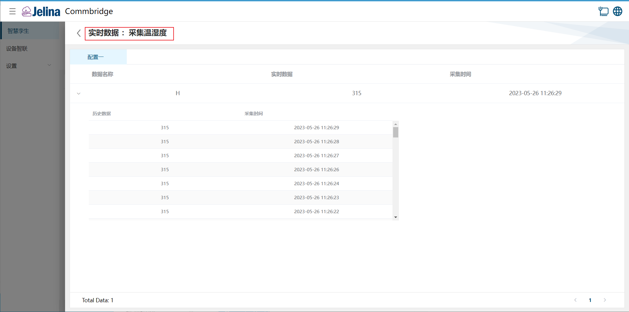
(3) Select a scheme to view real-time and historical point data in its groups.
Acquired real-time values are hexadecimal.
4. Configuration reference
Section titled “4. Configuration reference”Connection settings
Section titled “Connection settings”| Parameter | Description | Format | Example | Notes |
|---|---|---|---|---|
| Scheme name | User-defined scheme name | Nonempty | Temperature/humidity acquisition | |
| Interface | Actual serial interface on the device | ttyS0, ttyS1 | ttyO3 | Usually RS485; depends on USB connection order |
| Data bits | Number of data bits in each unit | 7, 8 | 8 | |
| Stop bits | Marks the end of a packet | 1, 2 | 1 | |
| Parity | Simple serial error checking | Odd, Even, or None | None | |
| Baud rate | Symbols transmitted per second | 11520, 57600, 38400, 19200, 9600, or 4800 | 19200 |
Data frame configuration
Section titled “Data frame configuration”| Parameter | Prerequisite | Description | Format | Example | Notes |
|---|---|---|---|---|---|
| Name | User-defined name | Nonempty; cannot start with a digit or contain . , [ ] { } ( ) ; = | Distance group 1 | ||
| Frame mode | Data frame transmission mode | HEX, ASCII | HEX | ASCII is rarely used | |
| Frame format | Depends on frame mode | Regex: ^(?:[0-9a-fA-F]{2} )*[0-9a-fA-F]{2}$ | Space-separated hexadecimal string | 0f 03 00 00 00 01 85 24 | |
| Cycle time (ms) | Number | 1000 | |||
| Enabled | If disabled, it cannot appear or be configured in frame parsing | disabled, enabled | enabled |
Note: Serial can read only 20 data items at a time.
Data frame parsing
Section titled “Data frame parsing”| Parameter | Description | Format | Example | Notes |
|---|---|---|---|---|
| Name | User-defined name | Nonempty | H | |
| Parsing | byte[3]byte[4] | |||
| Enabled | If disabled, it cannot appear or be configured in frame parsing | disabled, enabled | enabled |
5. Serial protocol parameter details
Section titled “5. Serial protocol parameter details”Frame modes:
- HEX: hexadecimal, using 16 characters from 0 to F.
- ASCII: a character set representing 128 characters.
ASCII and Hex differ primarily in the range of characters they represent.
The following HEX request is a Modbus RTU example for reading holding registers (function code 0x03):
| Device address [1 byte] | Function code [1 byte] | Start address [2 bytes] | Register count [2 bytes] | CRC [2 bytes] |
|---|---|---|---|---|
| address | 03 | AddrH AddrL | NumH NumL | CRCL CRCH |
CRC (cyclic redundancy check) uses CRC-16/MODBUS with polynomial X16+X15+X2+1. The checksum low byte is transmitted first.
Example: 01 03 00 10 00 01 85 CF
| Command | 01 | 03 | 00 | 10 | 00 | 01 | 85 | CF |
|---|---|---|---|---|---|---|---|---|
| Meaning | Device address | Read command | Register start address high byte | Register start address low byte | Read quantity high byte | Read quantity low byte | CRCL | CRCH |
The following is a Modbus ASCII request for reading holding registers (function code 0x03). Each raw byte is encoded as two ASCII hexadecimal characters. The table excludes the starting colon (:) and ending CR/LF characters:
| Device address [2 characters] | Function code [2 characters] | Start address [4 characters] | Register count [4 characters] | LRC [2 characters] |
|---|---|---|---|---|
| address | 03 | AddrH AddrL | NumH NumL | Two hexadecimal characters of the LRC |
LRC (longitudinal redundancy check) sums the raw address, function-code, and data bytes, discards carries beyond 8 bits, and takes the two’s complement to produce a one-byte checksum. The starting colon (:) and ending CR/LF are excluded.