Acquire Modbus Slave data over Modbus RTU
1. Objective
Section titled “1. Objective”Simulate a Modbus RTU slave with the Modbus Slave tool. Acquire its data using Modbus Client (Master), process it, and display results in real time.
2. Simulator, device, and plugins
Section titled “2. Simulator, device, and plugins”- Simulator
Modbus Slave simulates slave devices, receiving master command packets and returning data packets.
Simulated connection and point settings:
| key | name |
|---|---|
| Protocol (Connection) | Serial Port |
| Baud rate | 19200 |
| Data bits | 8 |
| Parity | None |
| Stop bits | 1 |
| Slave ID | 1 |
| Register type | Holding Registers |
| Data type | Unsigned |
-
Device
RSB-3720
-
Plugins
Modbus Client (Master), Data Processing, and MQTT Upload
3. Rules
Section titled “3. Rules”(1) Connect the computer and device using USB.
(2) Simulate three points in Modbus Slave.
- Protocol: Modbus RTU.- Register type: Holding Register.- Data type: uint16.- Byte order: big-endian (AB).- Point addresses: 0, 1, and 2.(3) Acquire the three Modbus points over Modbus RTU as X, Y, and Z. Their formulas are {X}/10+8, {Y}*3.1412, and ({Z}-10)*5, respectively.
(4) The resulting connection scheme is:

4. Key steps
Section titled “4. Key steps”(1) Configure Modbus Slave.

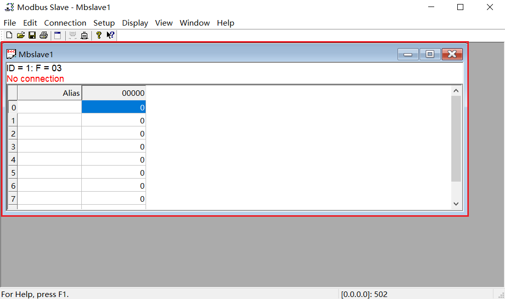
a. Open Modbus Slave → File → New to create an Mbslave.
- No Connection: no connected device.
- ID=1: slave ID is 1 and is configurable.
- F=3: Function 03 Holding Registers (4x), matching the acquisition plugin’s register type.
- Numbers 0–7 on the left are data addresses.
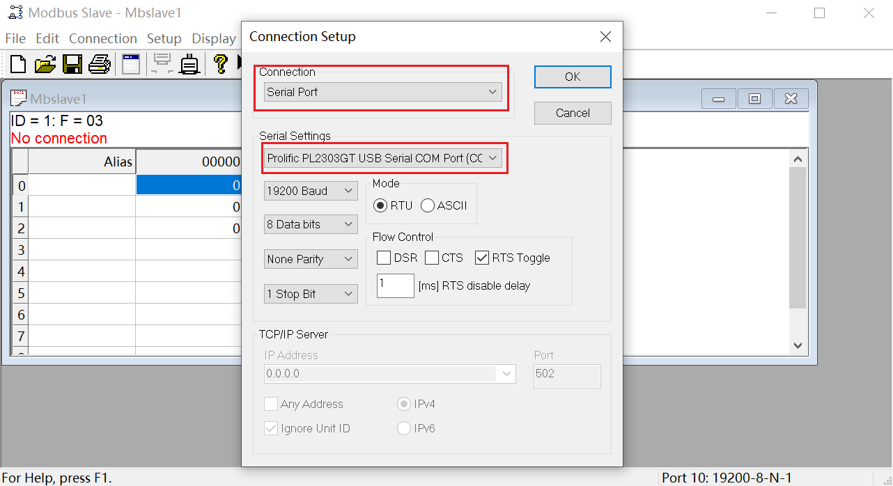
b. Select Connection → Connect…, enter parameters, and select OK.
- Connection: Serial Port.
- Serial Settings: serial connection configuration.
- Serial port: Prolific PL2303GT USB Serial COM Port (COM8).
- Baud rate: 19200 Baud.
- Data bits: 8 Data bits.
- Parity: None Parity.
- Stop bits: 1 Stop Bit.
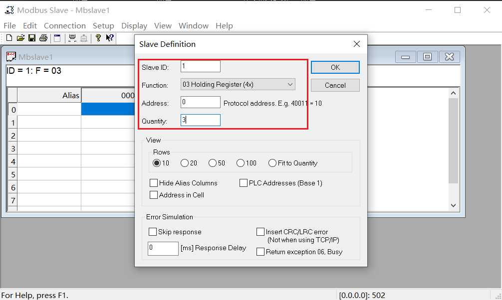
c. Select SetUp → Slave Definition…, enter parameters, and select OK.
- Slave ID: slave address ID, default 1.
- Function: 03 Holding Register (4x).
- Address: 0.
- Quantity: 3 registers.
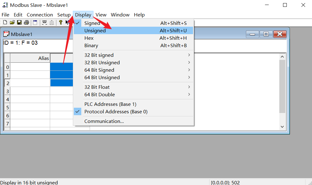
d. Select the three points, then Display → Unsigned.
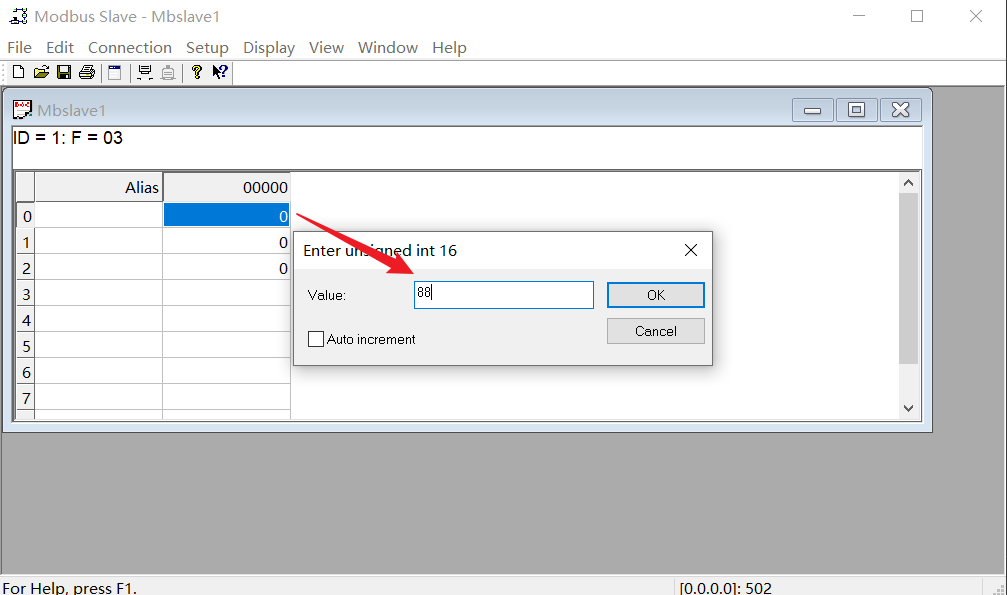
e. Double-click the first row, enter value 88, and select OK.
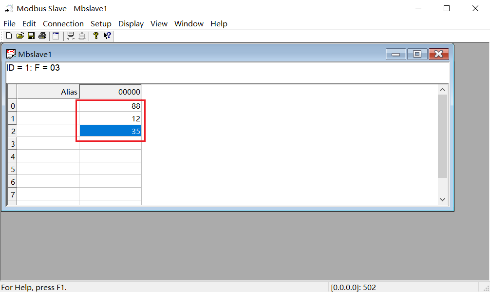
f. Set the second and third points to 12 and 35.
(2) Configure acquisition in Modbus Client (Master).
a. Connection settings. Scheme name is required.
Match the simulator parameters:
- Scheme name: RTU acquisition
- Protocol: Modbus RTU
- Interface: ttyUSB5
- Baud rate: 19200
- Data bits: 8
- Parity: None
- Stop bits: 1
- Synchronous acquisition: Yes
- Acquisition interval (ms): 1000
- Timeout: 500
- Data freshness (ms): 500
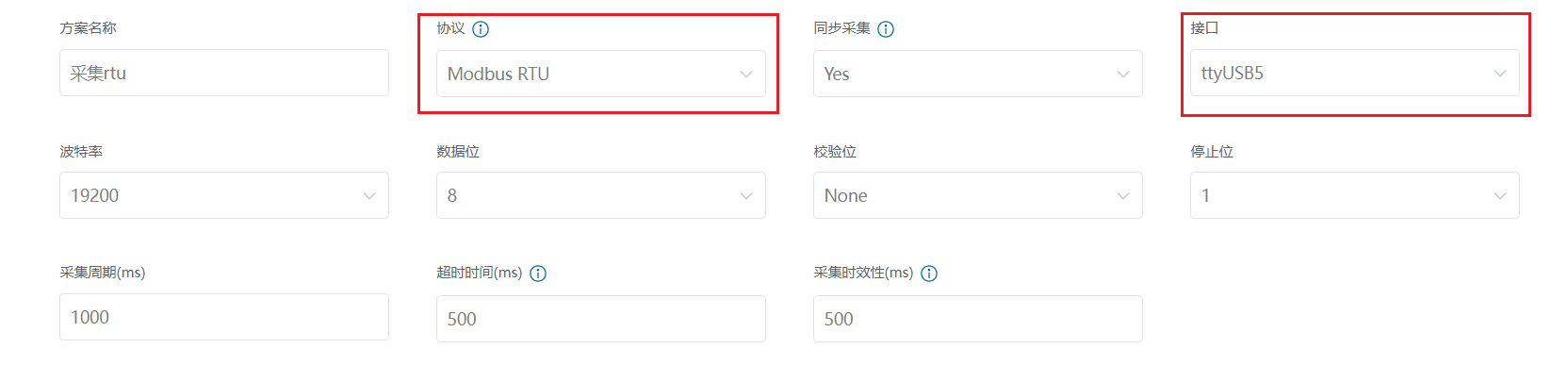
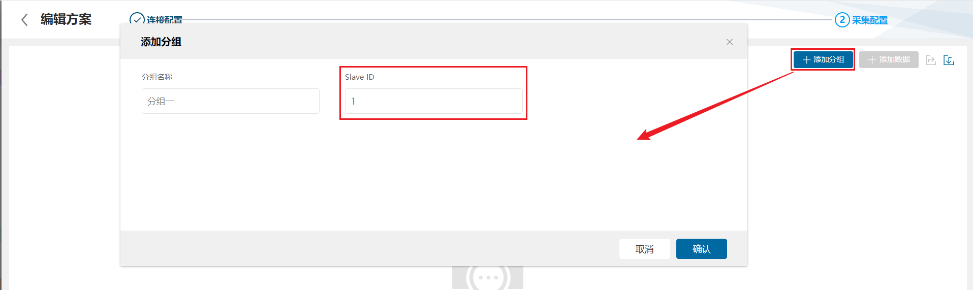
b. Add a group.
Select Add group, enter these values, and select Finish:
- Group name: Group 1
- Slave ID: 1
Note: IP, port, and Slave ID must match the simulator; the IP is the address of the computer running it.
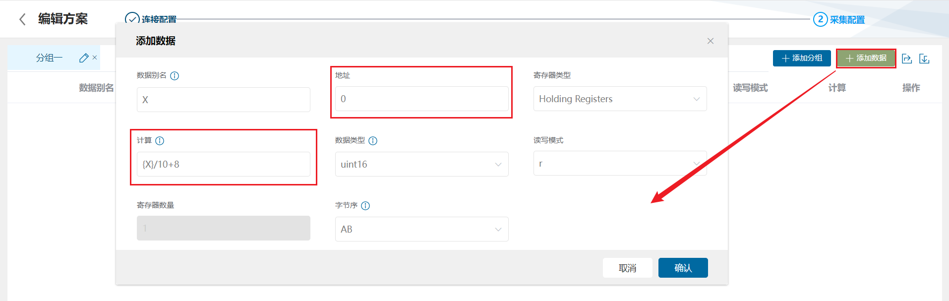
c. Add points.
Select Add data, enter these values, and confirm:
- Data alias: X
- Address: 0
- Register type: Holding Registers
- Data type: uint16
- Register count: 1
- Byte order: AB
- Read/write mode: r
- Calculation: {X}/10+8

5. Results
Section titled “5. Results”(1) Select Deploy under Device Connectivity and wait for success.
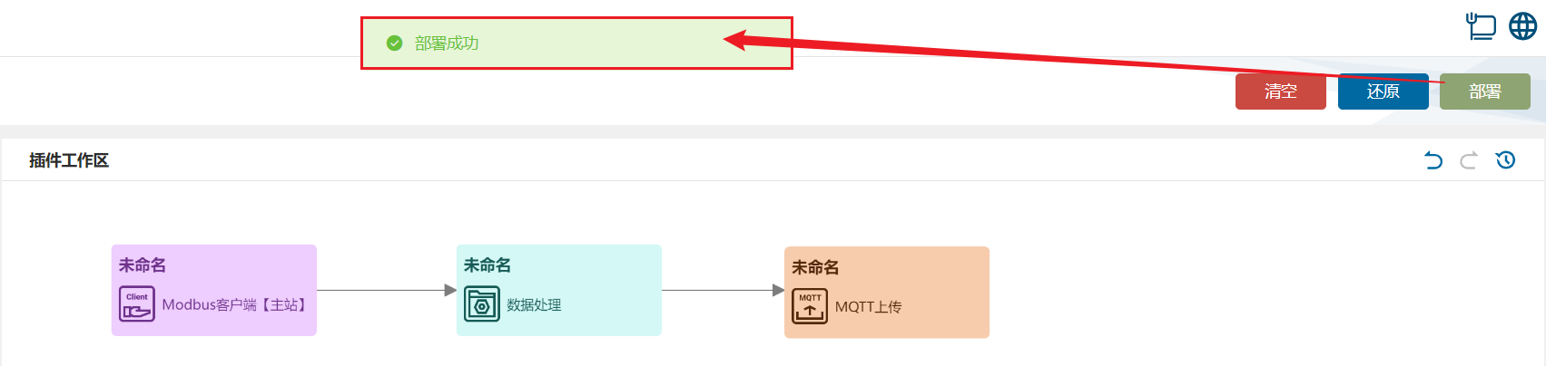
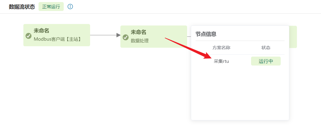
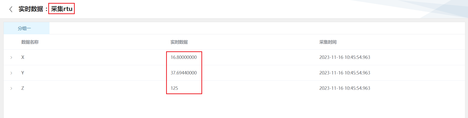
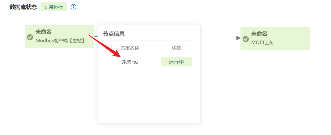
(2) Switch to Digital Twin, hover over Modbus Client (Master), select RTU acquisition, and view acquired real-time data.
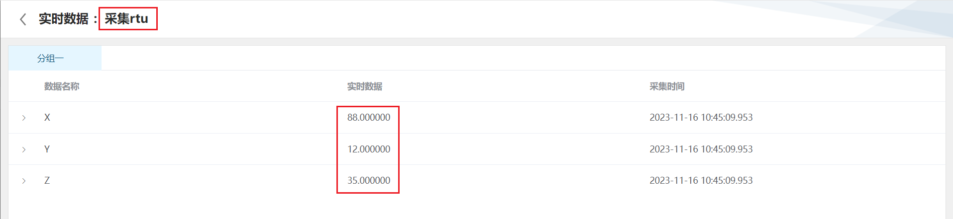
(3) Hover over Data Processing, select RTU acquisition, and view processed real-time data.