
Trigger Console
1. Prerequisites
Section titled “1. Prerequisites”(1) Configure an IEC104 acquisition point named Current value, with an increasing value.
(2) Configure a Modbus TCP point M, with value=100.
2. Create nodes
Section titled “2. Create nodes”(1) Open CommBridge Digital Twin and switch to Device Connectivity on the left.
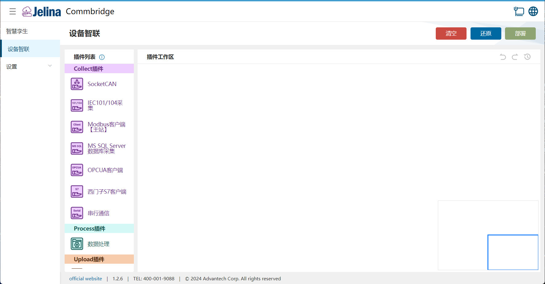
(2) Drag IEC104 Acquisition, Trigger Console, and Modbus Client (Master) into the workspace to create three nodes.

(3) Connect them in order: IEC104 Acquisition → Trigger Console → Modbus Client (Master).

3. Create a scheme
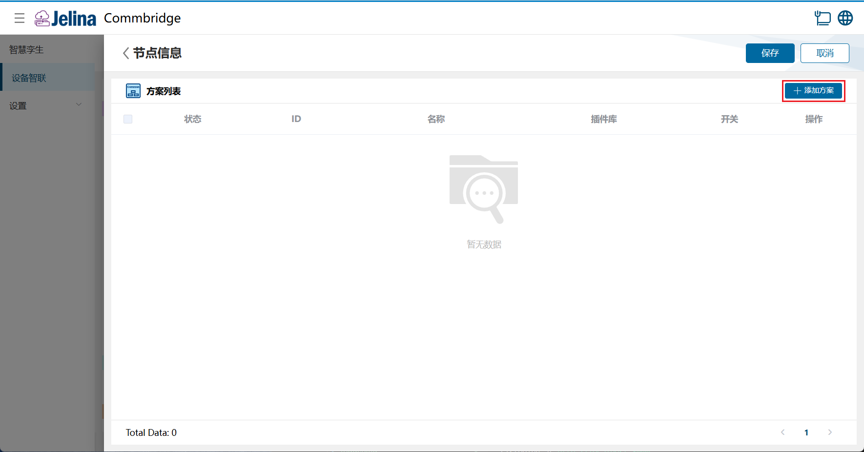
Section titled “3. Create a scheme”(1) Double-click Trigger Console and select Add scheme.
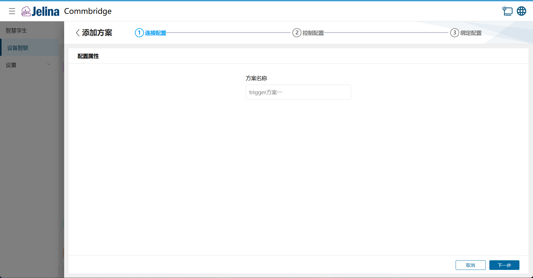
(2) Enter connection settings and select Next.
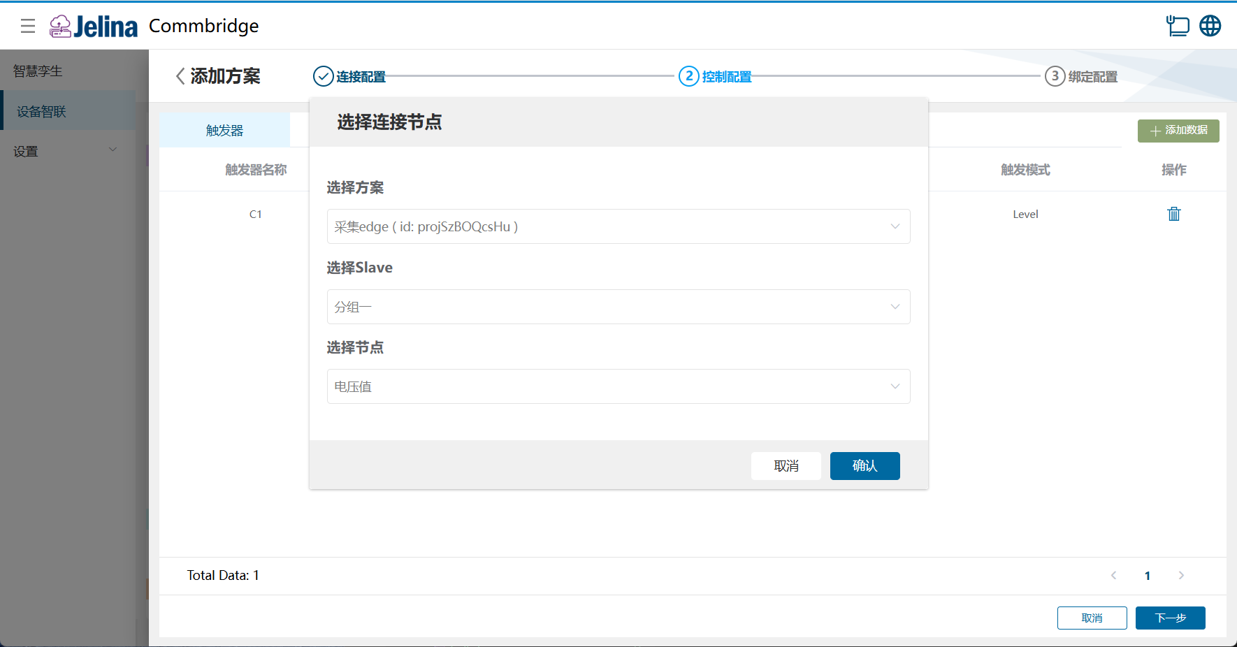
(3) Select Add data under Triggers and configure it.
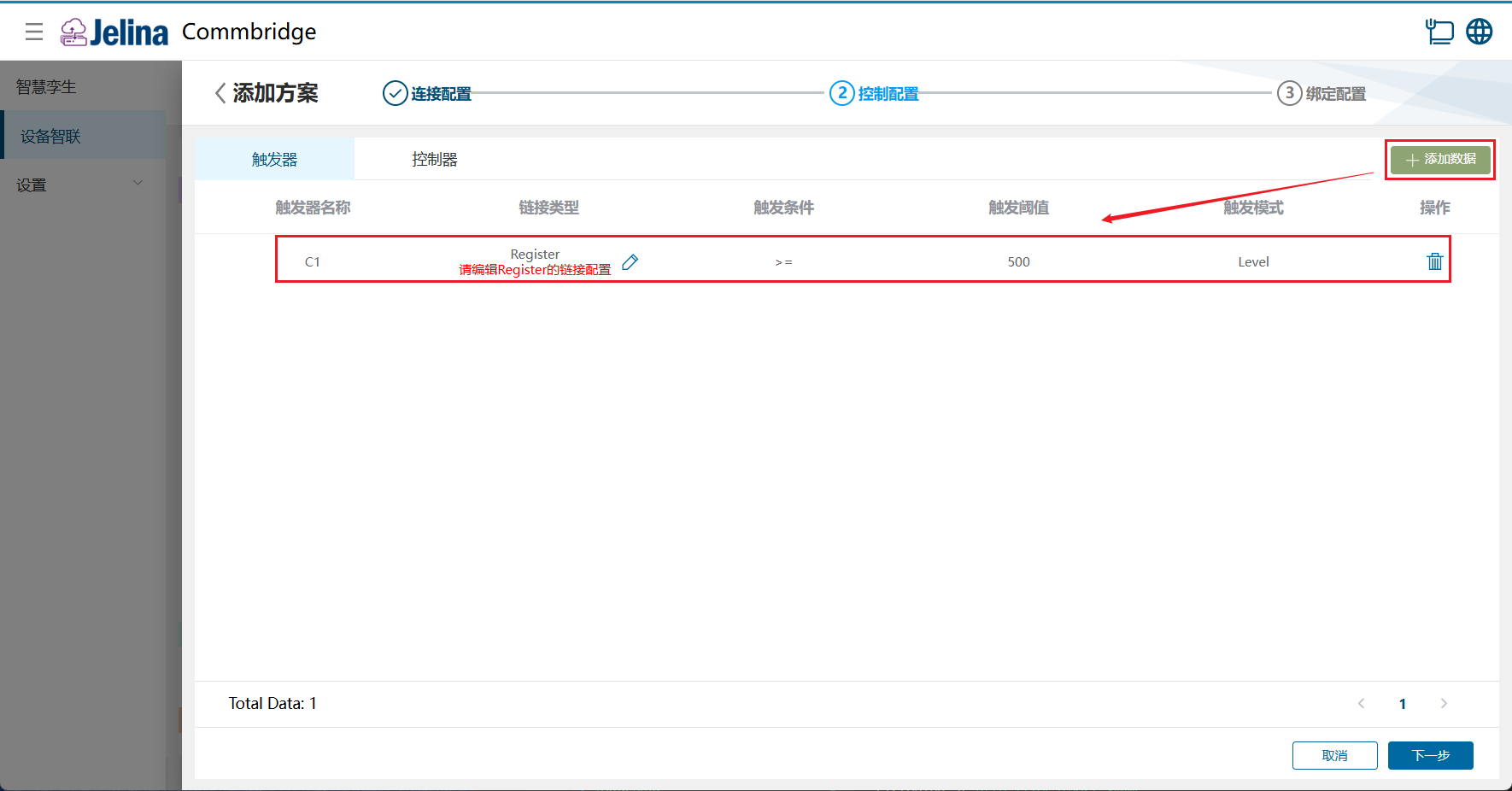
(4) Select Edit beside Register, choose the upstream acquisition scheme, and confirm.
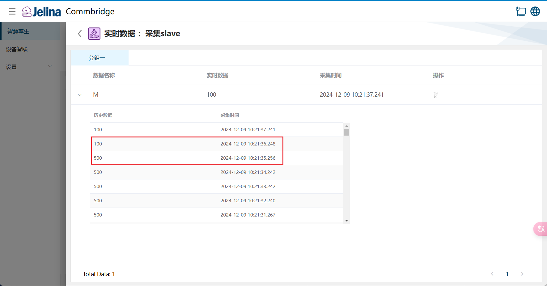
Trigger C1 becomes active when Current value >= 500.
(5) Select Add data under Controllers and configure it.
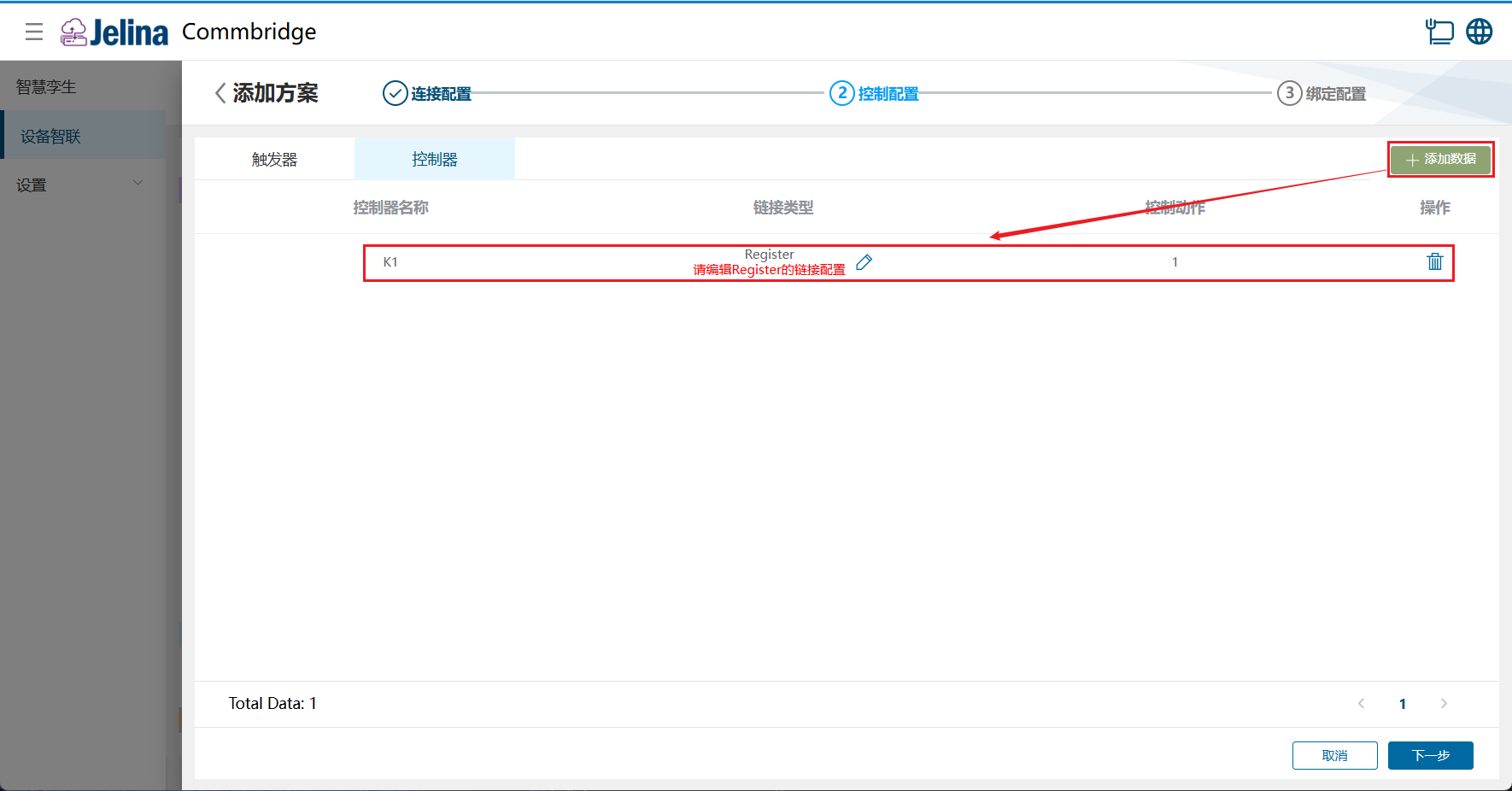
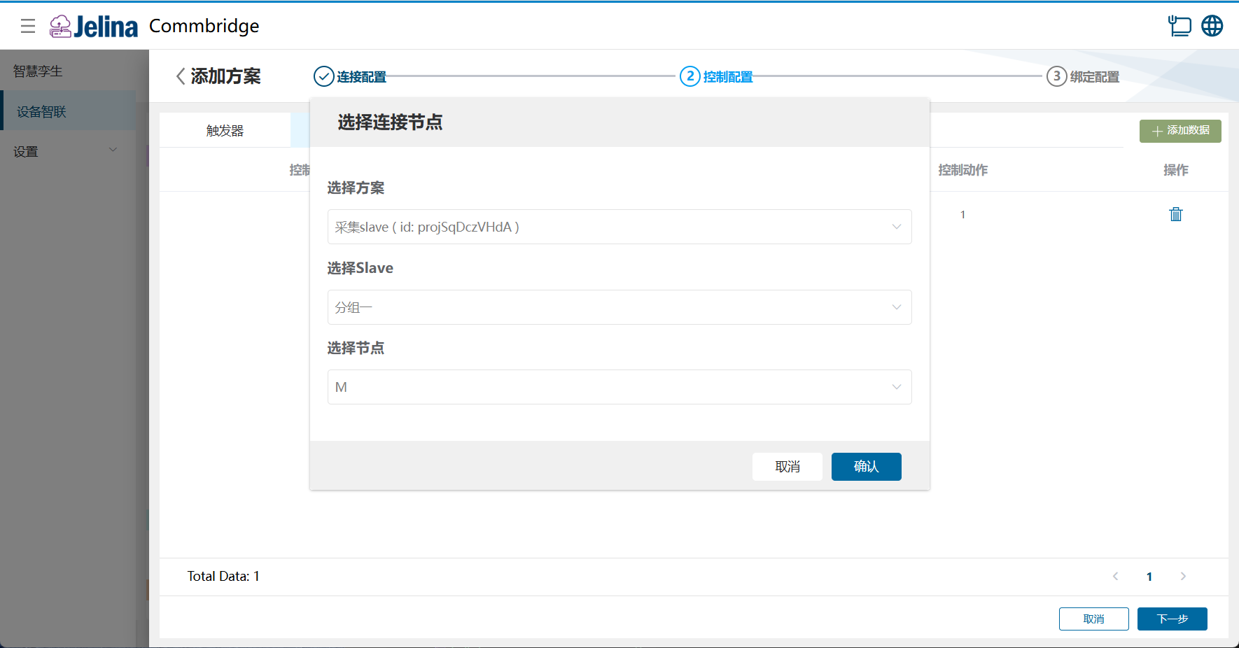
(6) Select Edit beside Register, choose the downstream acquisition scheme, and confirm.
Set M = 1.
(7) Select Next, select Add data, and configure the binding.
Triggers and controllers have a one-to-many relationship.
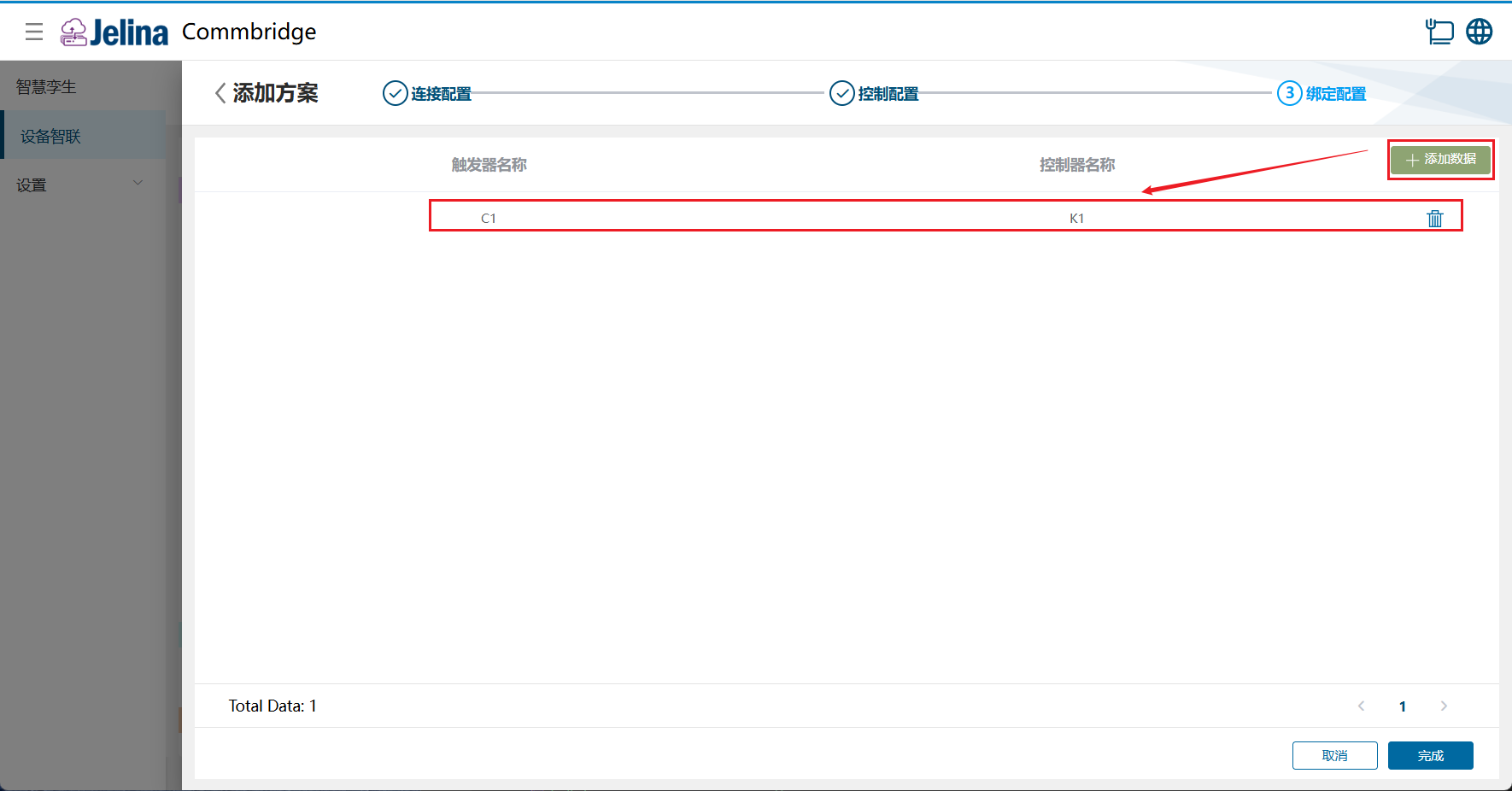
(8) Select Finish to add the control scheme.
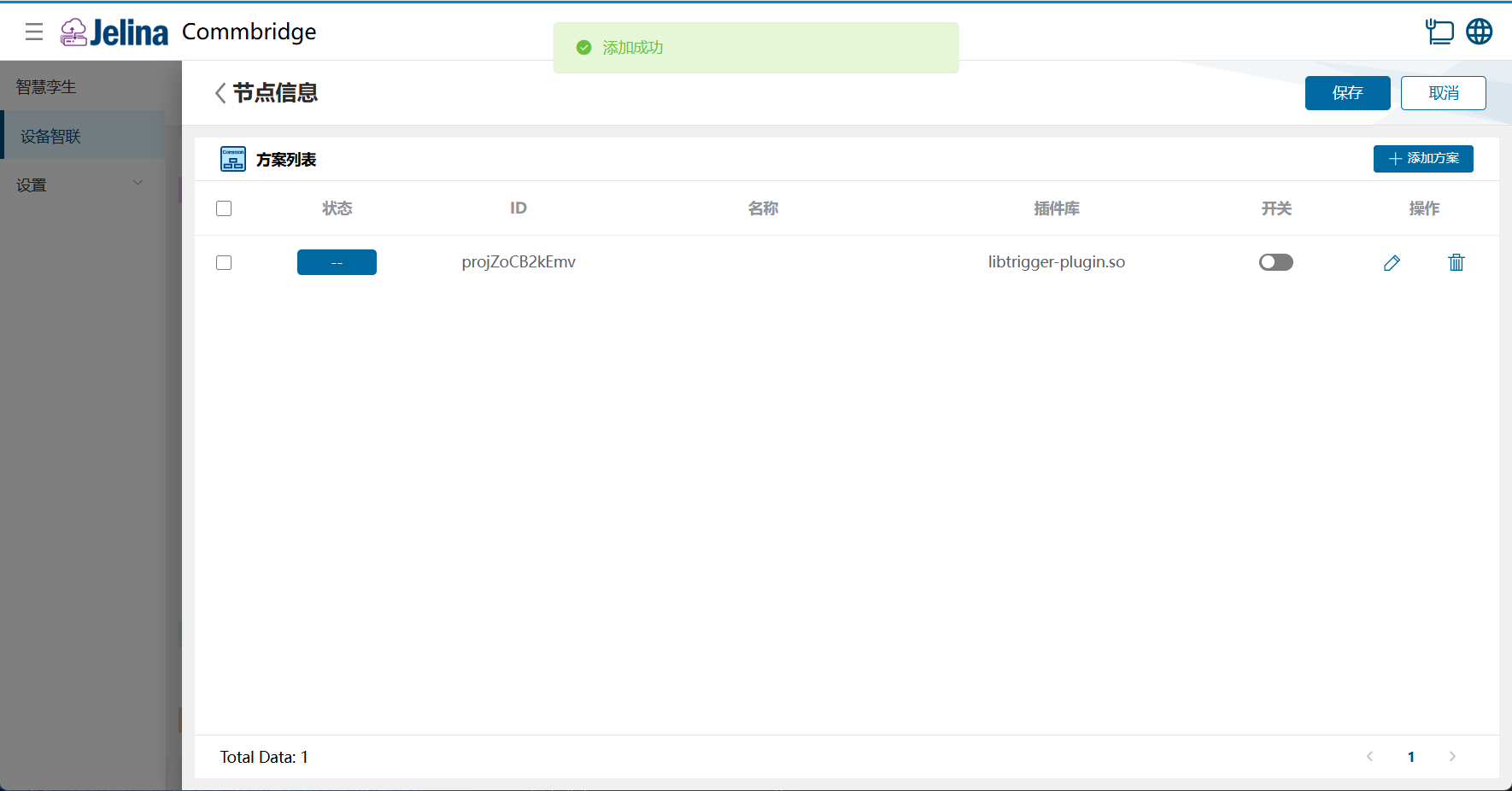
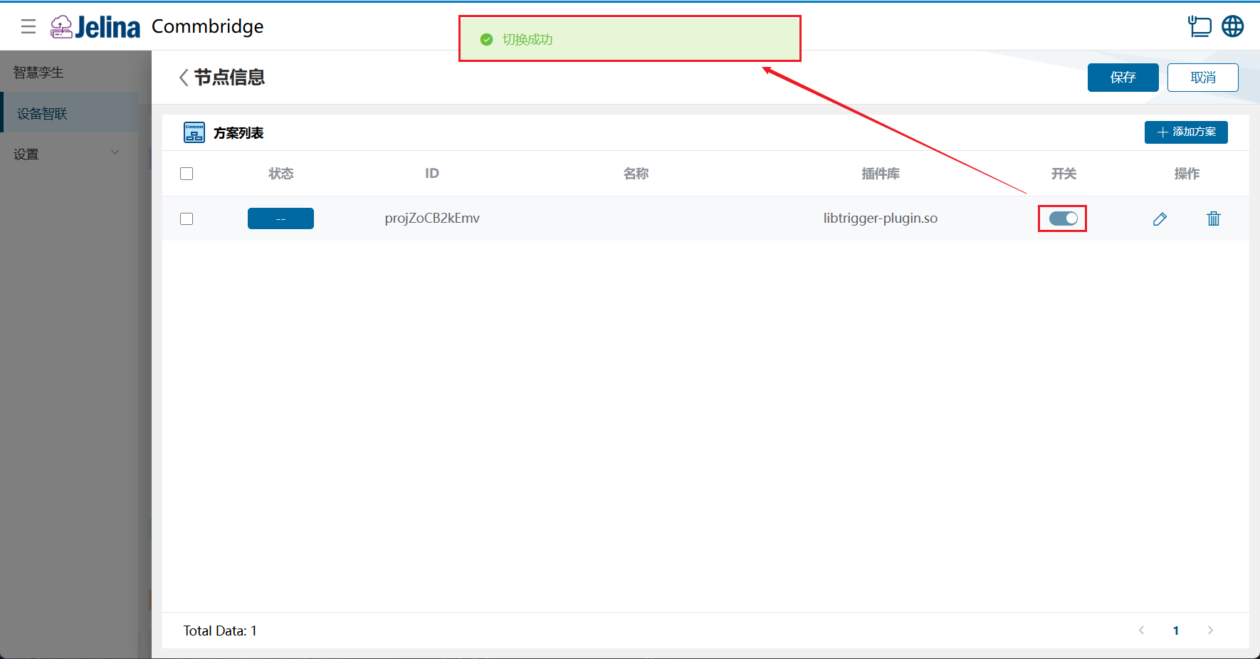
(9) Enable the scheme and select Save.
4. View results
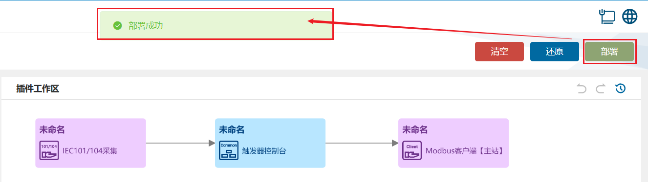
Section titled “4. View results”(1) Select Deploy under Device Connectivity and wait for success.
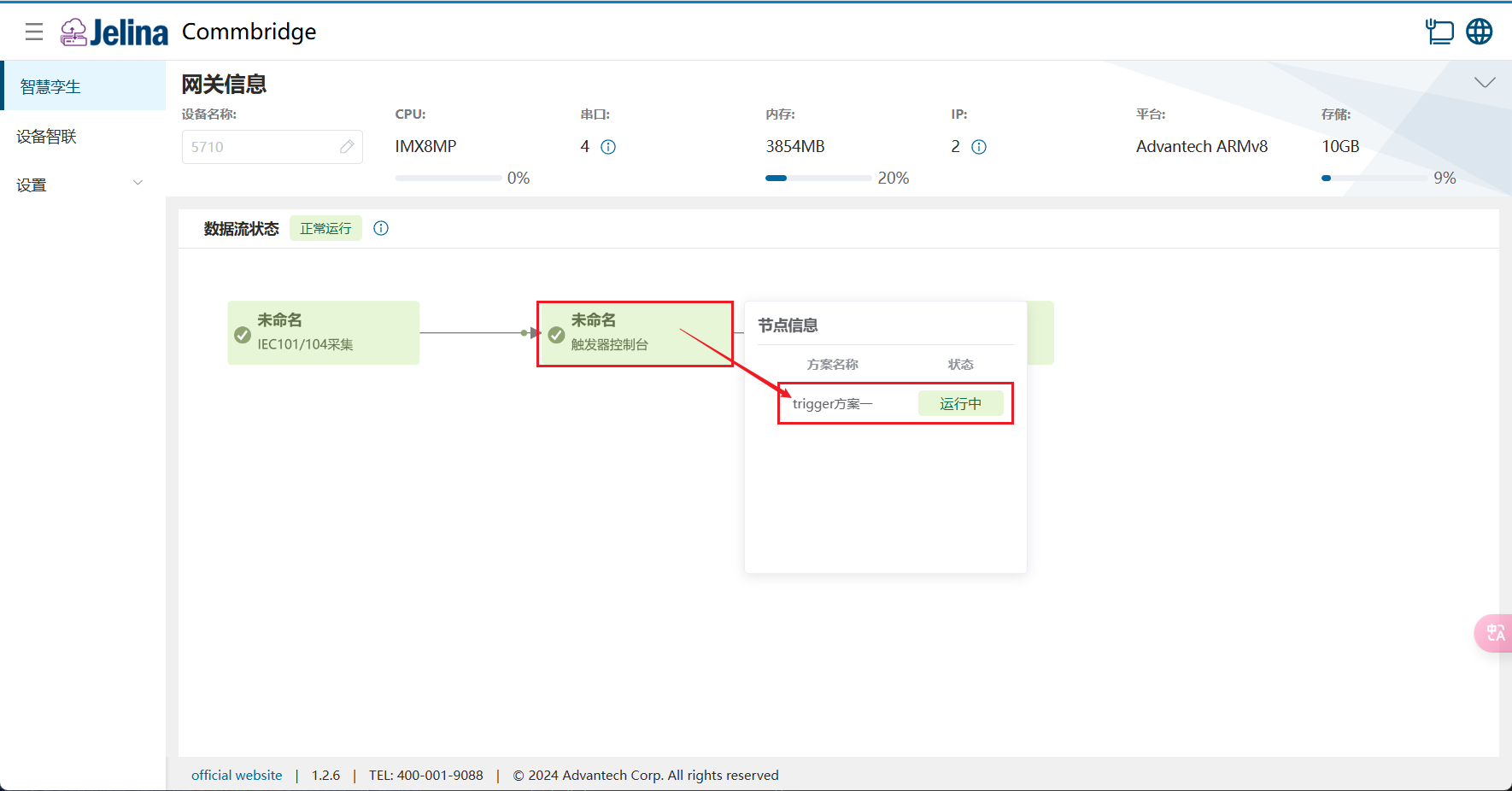
(2) Switch to Digital Twin and hover over Trigger Console and Modbus Client (Master) to view node information.
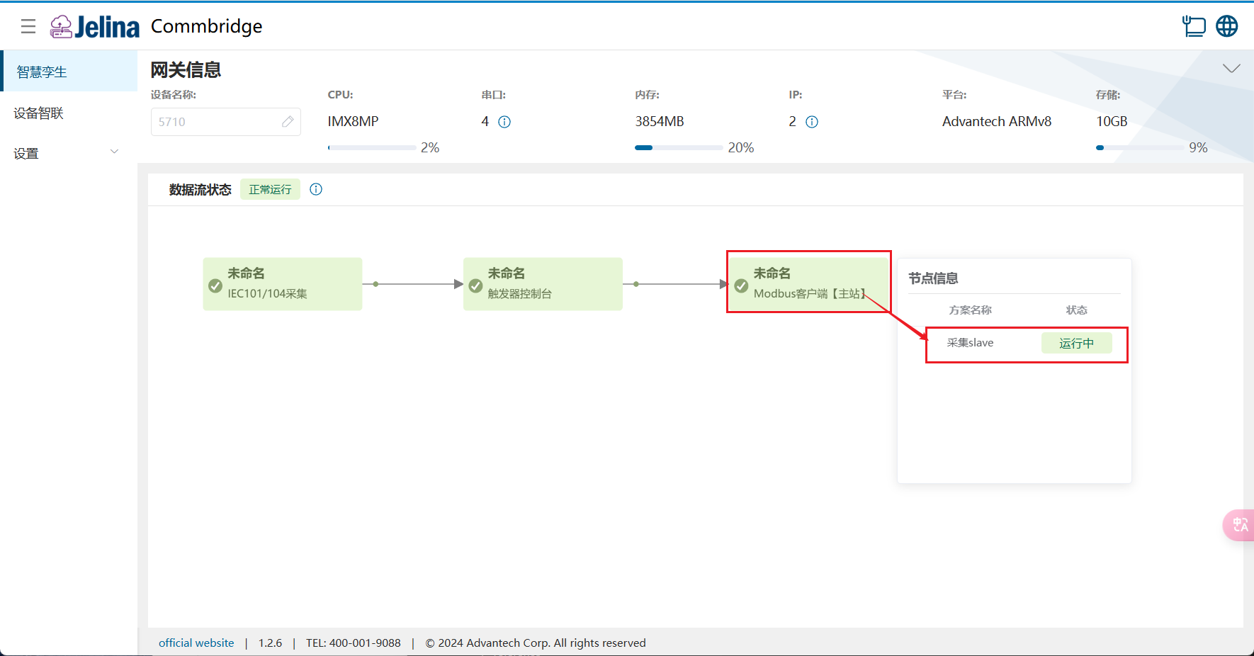
(3) Select a scheme to view real-time and historical point data in each group.
5. Configuration reference
Section titled “5. Configuration reference”Connection settings
Section titled “Connection settings”| Parameter | Description | Format | Example |
|---|---|---|---|
| Scheme name | User-defined scheme name | Nonempty | Trigger scheme 1 |
Triggers
Section titled “Triggers”| Parameter | Description | Format | Example |
|---|---|---|---|
| Trigger name | User-defined data name | Nonempty | C1 |
| Link type | Device GPIO or an upstream acquisition point | GPIO or Register | Register |
| Condition | Six comparison operators; see below | Dropdown | >= |
| Threshold | Monitored comparison value | Number | 500 |
| Trigger mode | Two triggering modes; see below | Level or Edge | Level |
- Link configuration:
- For GPIO, select Edit and choose the GPIO pin.
- For Register, select a scheme in an upstream acquisition plugin.
- Conditions: greater than, less than, equal, greater than or equal, less than or equal, and not equal.
- Trigger modes:
- Level: triggers continuously while the condition holds.
- Edge: triggers once when the condition changes from false to true. For a condition >10, it triggers when the value changes from <=10 to >10. Remaining above 10 does not trigger again until the value returns to <=10 first.
Controllers
Section titled “Controllers”| Parameter | Description | Format | Example |
|---|---|---|---|
| Controller name | User-defined data name | Nonempty | K1 |
| Link type | Device GPIO or a downstream acquisition point | GPIO or Register | Register |
| Control action | GPIO action or custom value | Nonempty | 1 |
- Link configuration:
- For GPIO, select Edit and choose the GPIO pin.
- For Register, select a scheme in a downstream acquisition plugin.
- Control actions:
- GPIO supports Pull down or Pull up.
- Register supports custom data or arithmetic expressions.
- A trigger and controller cannot select the same GPIO pin simultaneously.
Bindings
Section titled “Bindings”| Parameter | Description | Format | Example |
|---|---|---|---|
| Trigger name | Triggers already defined in control configuration | Dropdown, single selection | C1 |
| Controller name | Controllers already defined in control configuration | Dropdown, multiple selection | K1 |