
CAN acquisition
1. Create nodes
Section titled “1. Create nodes”(1) Open CommBridge Digital Twin and switch to Device Connectivity.
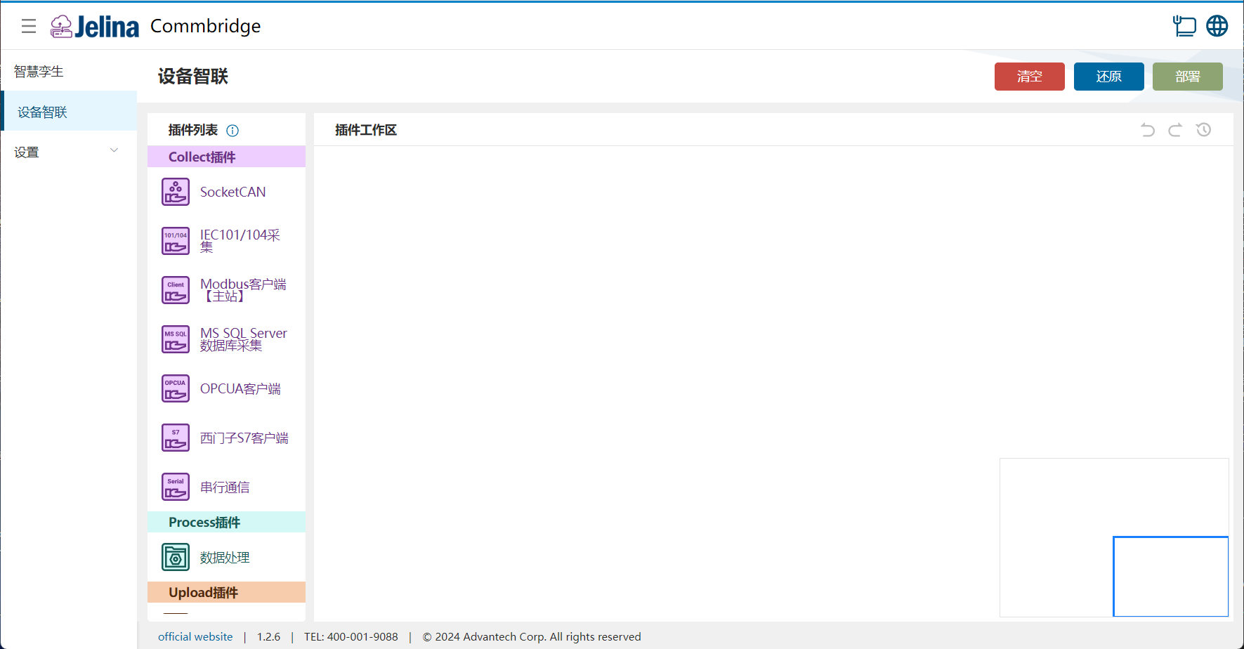
(2) Drag SocketCAN, Data Processing, and MQTT Upload into the workspace to create three nodes.

(3) Connect SocketCAN → Data Processing → MQTT Upload.

2. Create a scheme
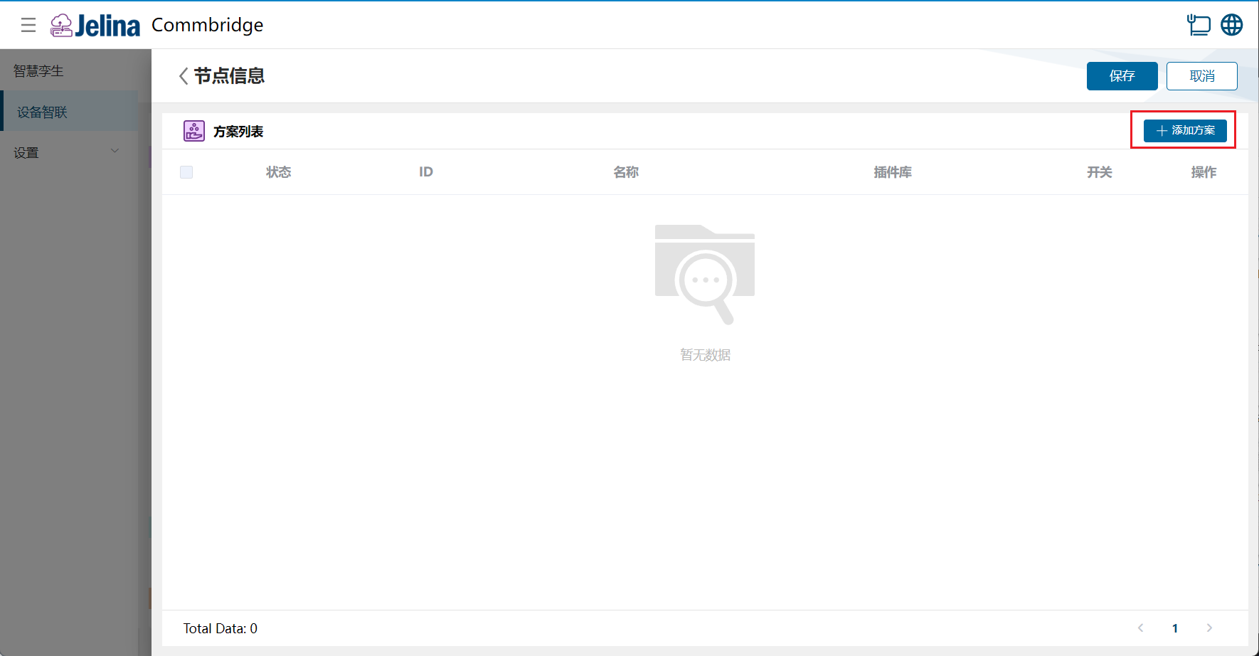
Section titled “2. Create a scheme”(1) Double-click SocketCAN and select Add scheme.
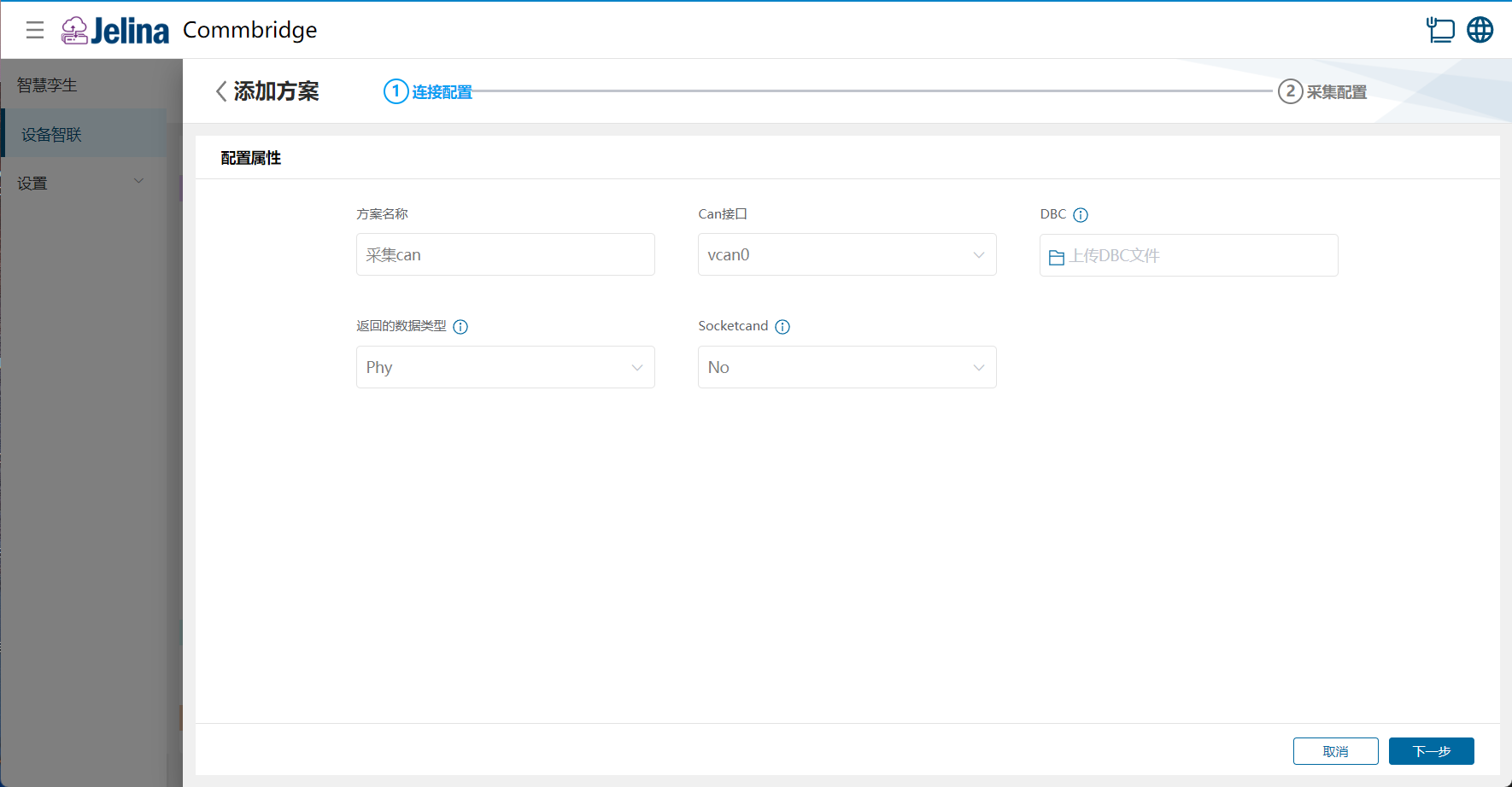
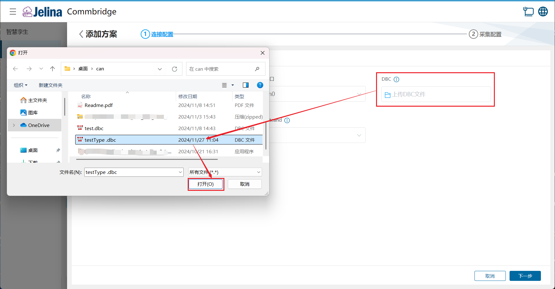
(2) Enter connection settings, import a DBC file, and select Next.
(3) Review group and point information.
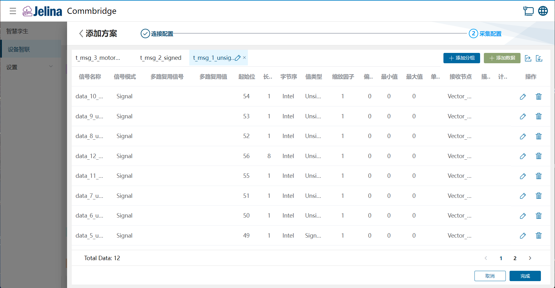
(4) Select Finish to add the acquisition scheme.
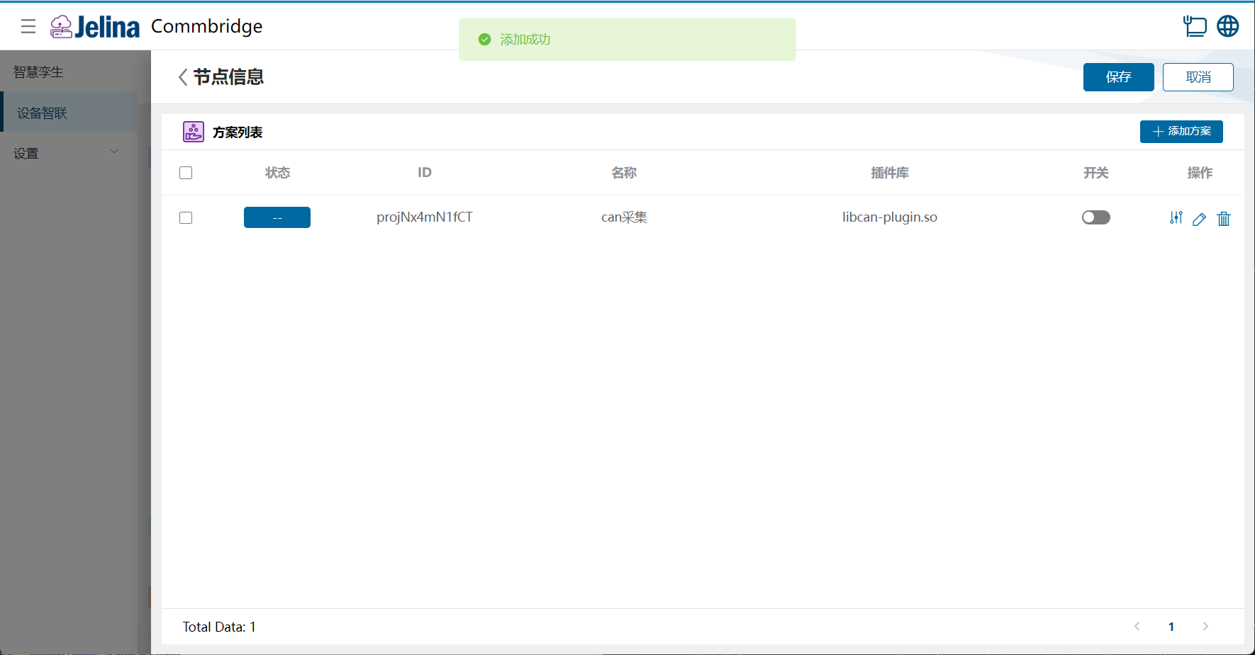
(5) Enable the scheme and select Save.
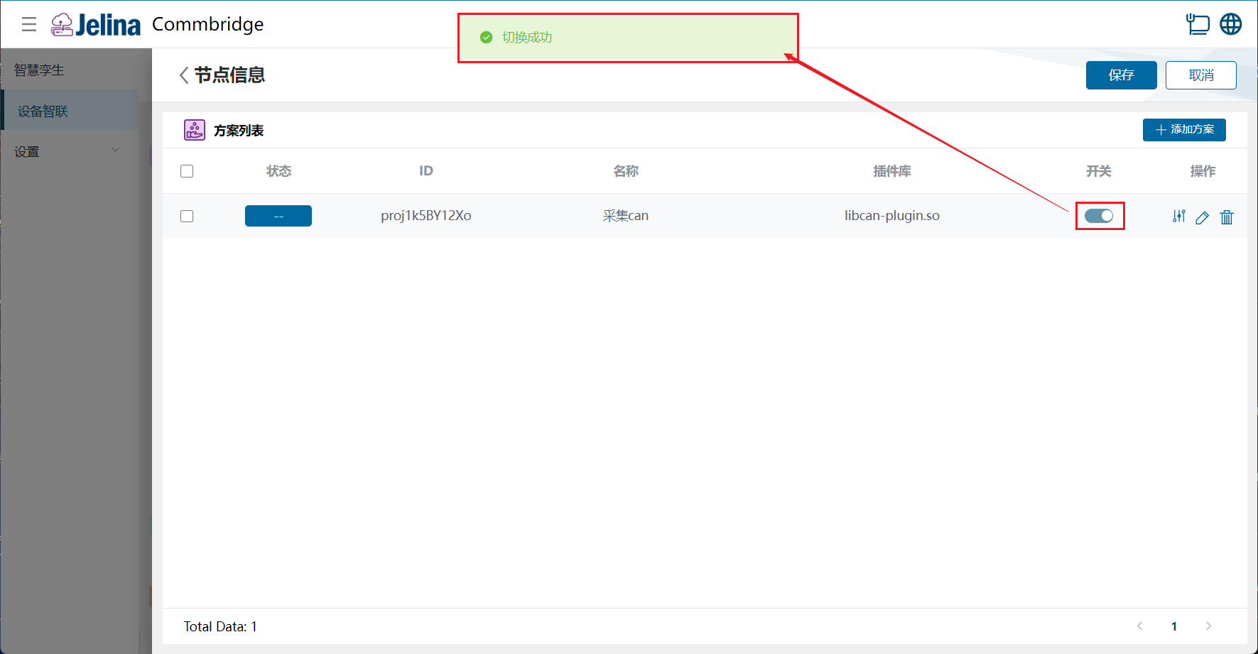
3. View results
Section titled “3. View results”(1) Select Deploy under Device Connectivity and wait for success.
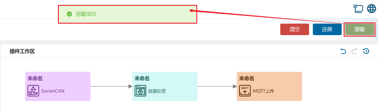
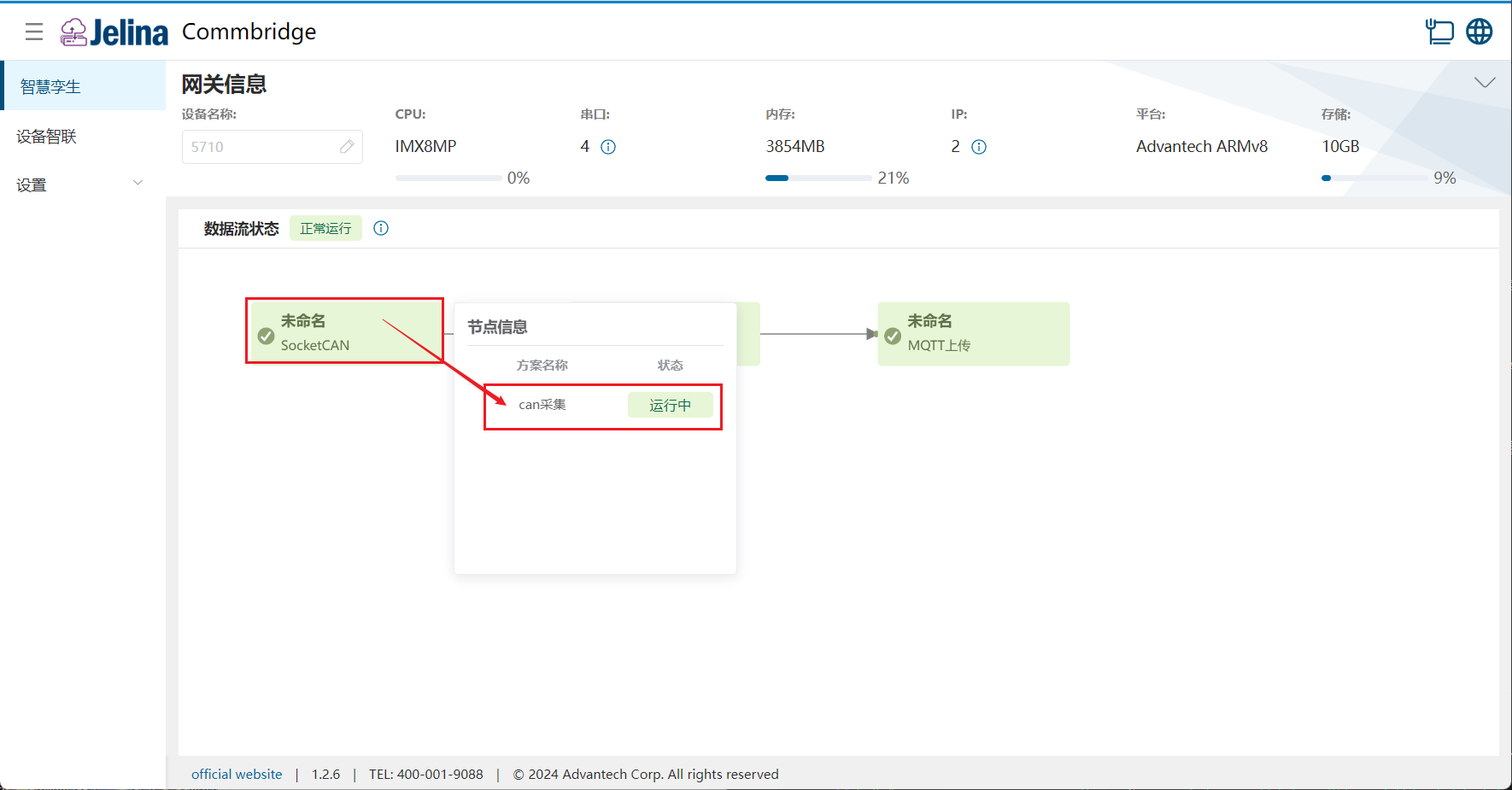
(2) Switch to Digital Twin and hover over SocketCAN to display node information.
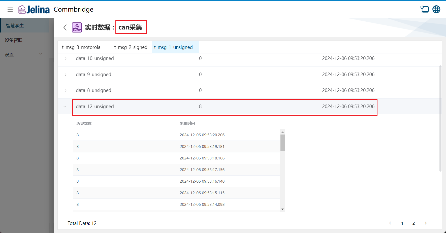
(3) Select a scheme to view real-time and historical point data in each group.
4. Configuration reference
Section titled “4. Configuration reference”Connection settings
Section titled “Connection settings”| Parameter | Description | Format | Example | Notes |
|---|---|---|---|---|
| Scheme name | User-defined scheme name | Nonempty | CAN acquisition | |
| CAN interface | Actual CAN interface on the device | Dropdown | vcan0 | |
| DBC | See below | DBC file | testType.dbc | |
| Returned data type | Type of acquired real-time values | Dropdown | Phy | |
| Throttle interval | Skip duplicate frames within this interval until it expires or data changes; 0 disables throttling | Nonempty number, [0,2147483647] | Phy | |
| Socketcand | Enable socketcand to access the computer’s CAN interface over a network interface | Yes, No | No | |
| Socketcand port | Used for remote data debugging | Number |
Note:
- DBC supplies the original data structure. Subsequent group/message and data/signal changes are merged into this DBC structure.
- Raw returns raw values; Phy returns physical values; PhyWIthUnit returns physical values with units.
- Communication uses TCP/IP and a dedicated protocol to carry CAN frames and control commands. Currently only Classical CAN is supported, not CAN FD.
Add groups
Section titled “Add groups”| Parameter | Description | Format | Example |
|---|---|---|---|
| Group name | User-defined group name | Nonempty | t_msg_1_unsigned |
| Message name | Describes the message’s function or purpose | Nonempty; letters, digits, and underscores only; cannot start with a digit | t_msg_1_unsigned |
| Message ID | Unique identifier distinguishing messages on the CAN bus | Nonempty decimal or hexadecimal number, [0x0-0xffffffff] | 0 |
| Data length code | Data length code (DLC): Classical CAN DLC 0–8 corresponds to 0–8 bytes. CAN FD DLC 0–8 also corresponds to 0–8 bytes; DLC 9–15 corresponds to 12, 16, 20, 24, 32, 48, and 64 bytes respectively. These protocol length definitions do not imply that the current plugin supports CAN FD. | Number, [0,8] or [0,15] | 8 |
| Transmitting node | Transmitter: the node sending the message | Dropdown, default Vector__XXX |
Vector__XXX |
| Message description | Optional explanation of message function | String |
Note:
- A group corresponds to a Message in the DBC file.
- Message IDs are usually 11-bit for standard frames or 29-bit for extended frames.
- If no transmitter is specified, use
Vector__XXX.
Add data
Section titled “Add data”| Parameter | Prerequisite | Description | Format | Example |
|---|---|---|---|---|
| Signal name | User-defined signal name describing its function | |||
| Signal mode | Signal transmission mode | Dropdown | ||
| Start bit | Zero-based signal starting position within the CAN frame | Bits | 0 | |
| Value type | Signal data type | Dropdown | Intel | |
| Byte order | Signal storage order within the message | Dropdown | ||
| Scaling factor | Factor converting raw values to physical values | Floating-point number | ||
| Offset | Offset for physical value calculation | Floating-point number | ||
| Minimum | Minimum physical value limiting the signal range | Floating-point number | ||
| Maximum | Maximum physical value limiting the signal range | Floating-point number | ||
| Unit | Physical unit | String | ||
| Receiving nodes | One or more target nodes receiving the signal | Dropdown, default Vector__XXX |
||
| Description | Physical unit, such as km/h, °C, or m/s | String | ||
| Calculation | User-defined formula based on data aliases | |||
| Length | Value type is Unsigned/Signed | Number of bits occupied by the signal | Bits, [1,64] | |
| Multiplex value | Signal mode is not Signal | Multiplexor value at which this signal becomes active |
Note:
- Signal modes: Signal, Multiplexor, Multiplexed.
- Value types: Unsigned, Signed, Float (single precision), Double (double precision).
- Byte order: Intel (little-endian) or Motorola (big-endian).
- Start bit: position of the least significant bit (LSB).
- End bit: position of the most significant bit (MSB).
- Resolution and offset convert physical and network values: network value = (physical value - offset) ÷ resolution.
- If no receiver is specified, use
Vector__XXX.
5. DBC file parameter details
Section titled “5. DBC file parameter details”A DBC (CAN Database File) is a standard format describing messages and signals on a Controller Area Network bus.
Components
Section titled “Components”(1) Node
A node logically represents a network device and may transmit or receive messages.
1). DBC format:
BU_: Node1 Node2 Node3BU_: defines the node list.- Node names follow, separated by spaces.
(2) Message
A message is the smallest transmitted data unit on the CAN network, containing multiple signals with a fixed ID and length.
1). DBC format:
BO_ <message-ID> <message-name>: <data-length-code> <transmitting-node>2). Example:
BO_ 1001 SpeedMessage: 8 Node1BO_: identifies a message.1001: message ID.SpeedMessage: message name.8: data length code (DLC).Node1: transmitting node.
(3) Signal
A signal is a data unit within a message representing a physical quantity such as speed, rotational speed, or temperature.
1). DBC format:
SG_ <signal-name> : <start-bit>|<length>@<byte-order><value-type-sign> (<scaling-factor>,<offset>) [<minimum>|<maximum>] "<unit>" <receiving-node>2). Example:
SG_ Speed : 0|16@1+ (0.1,0) [0|200] "km/h" Node2BO_: identifies a message.
Selected parameter explanations
Section titled “Selected parameter explanations”(1) Signal modes
| Signal mode | Meaning |
|---|---|
| Signal | Ordinary signal carrying data directly without special markers or relationships |
| Multiplexor | Selector signal determining which group of signals a message carries; for example, selects one of several data formats |
| Multiplexed | Signal bound to a multiplexor; the multiplexor value determines whether it is transmitted, such as a particular group sent when the selector equals 1 |