
IEC 104 Server
1. Configure the simulator
Section titled “1. Configure the simulator”Use the protocol simulator to generate data. Configure it as follows:
(1.) Double-click protocolsimulator.exe in its folder to open the protocol simulator.
(2.) Configure the following information in the simulator:
a. Connection parameter: TCP-S
b. IP: the laptop’s IPv4 address
c. Port: an integer greater than or equal to 1000, matching the port entered in Connection settings
d. Protocol type: iec104-server
e. Point list file: download simulator_point.csv, the point list for simulated measurement data, and upload it to the simulator
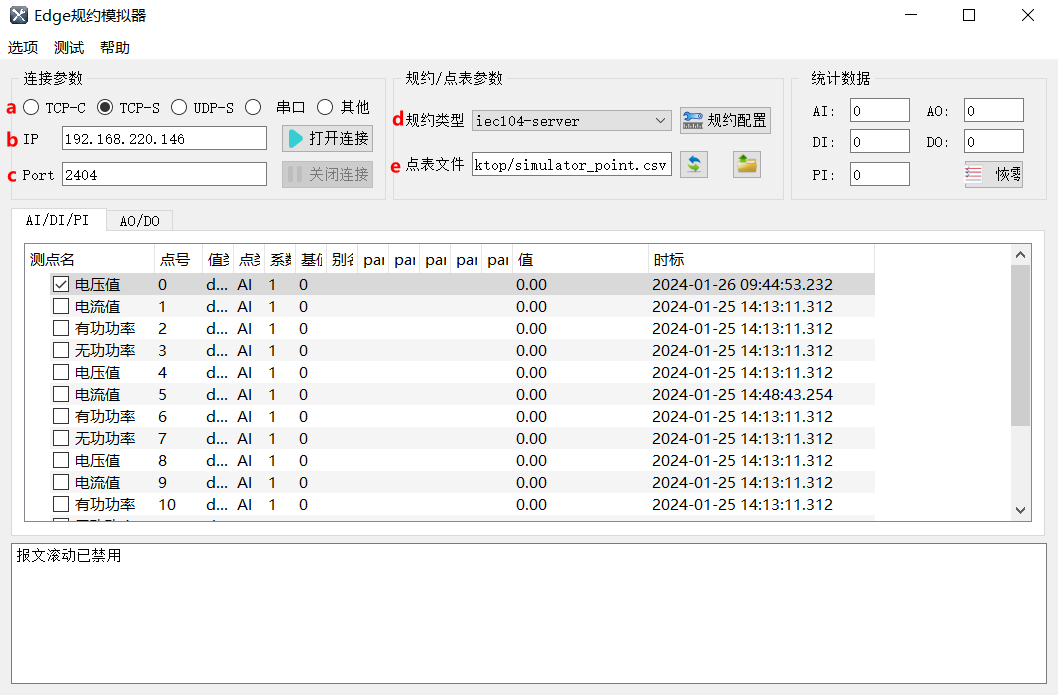
(3.) Select the required measurement points.
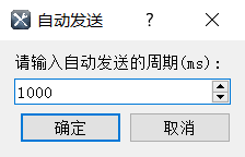
(4.) At the upper left, click Test → Auto Send, enter an interval of 1000ms, then click OK.
(5.) Click Open Connection to start generating simulated data.
2. Create nodes
Section titled “2. Create nodes”(1.) Open Digital Twin in CommBridge, then select Device Connectivity on the left.
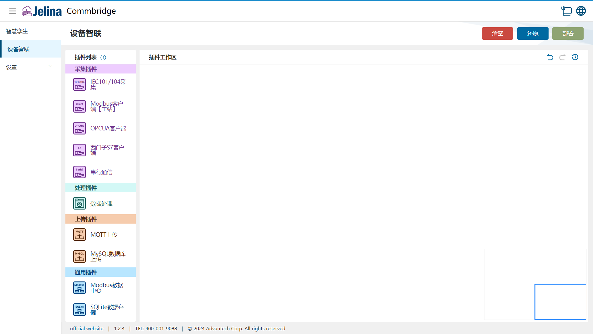
(2.) Drag the IEC104 Acquisition, Data Processing, and MQTT Upload plugins to the plugin workspace to create three nodes.

(3.) Connect the three nodes in this order: IEC104 Acquisition → Data Processing → MQTT Upload.

3. Create a scheme
Section titled “3. Create a scheme”(1.) Double-click IEC104 Acquisition, then click Add Scheme.
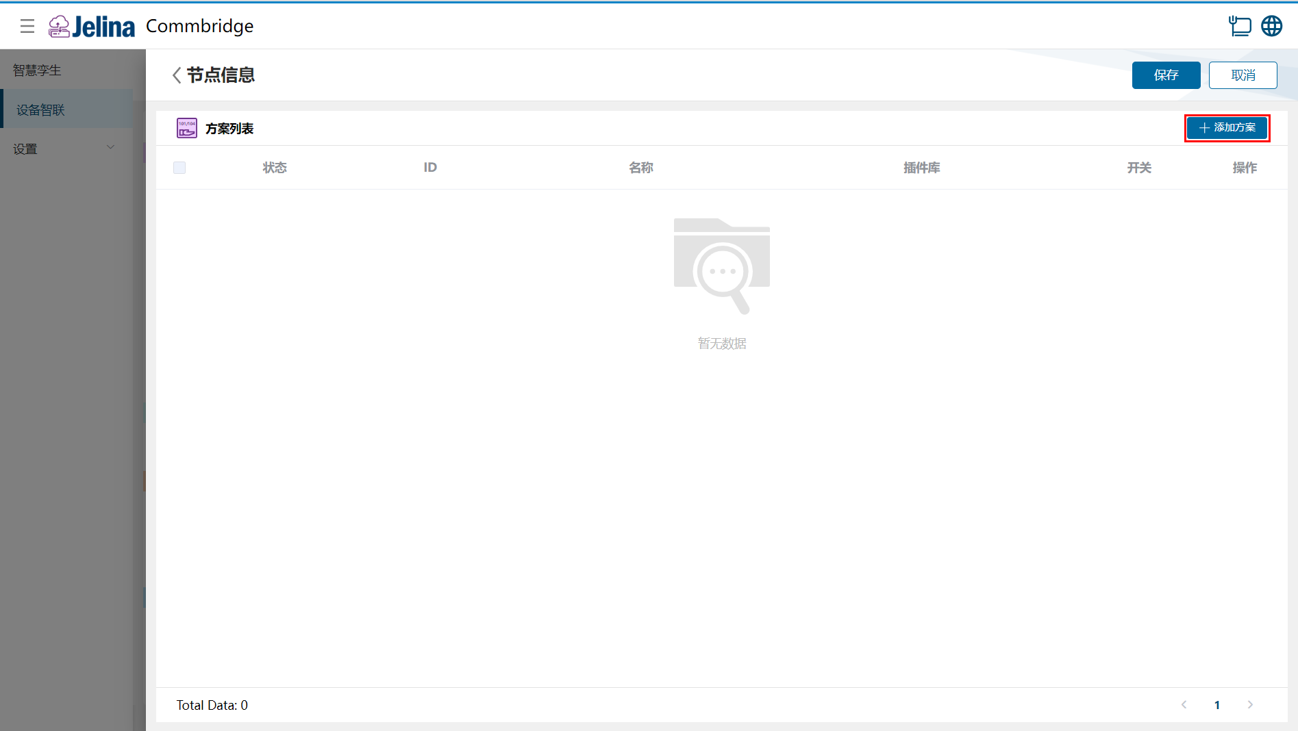
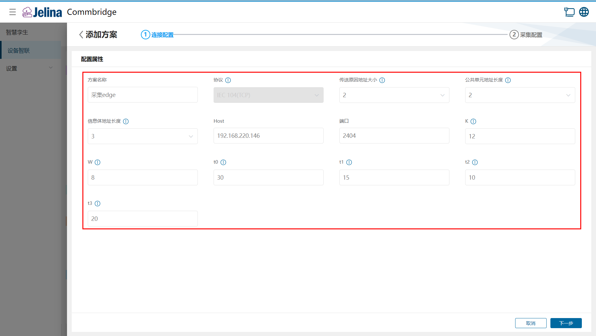
(2.) Enter the connection settings, then click Next.
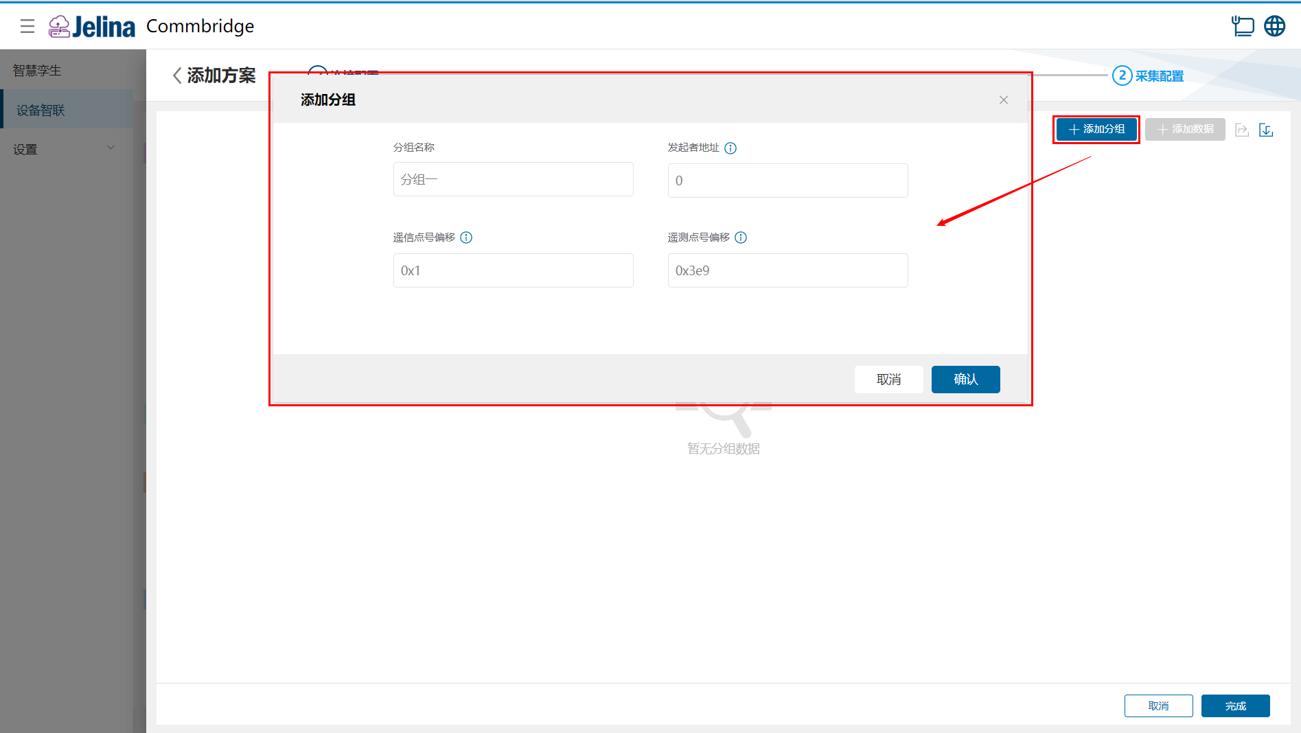
(3.) Click Add Group, enter the group settings, then click Confirm.
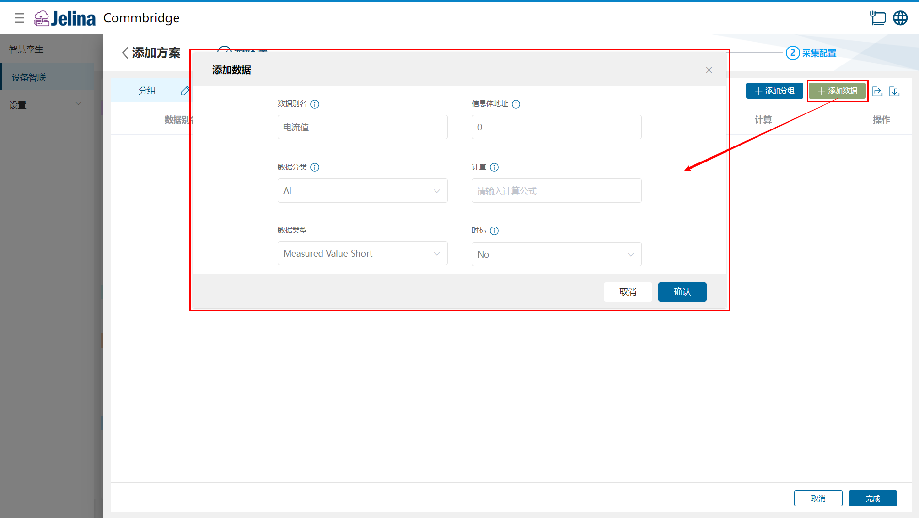
(4.) Click Add Data, enter the point settings, then click Confirm.
(5.) Click Finish to add the acquisition scheme.
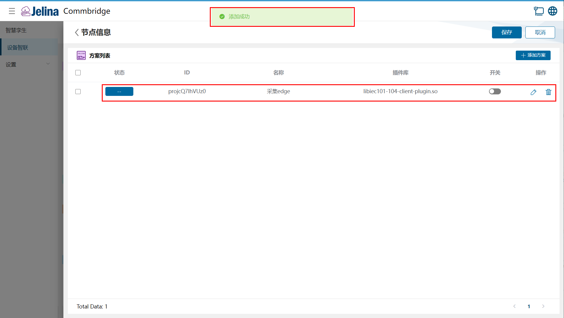
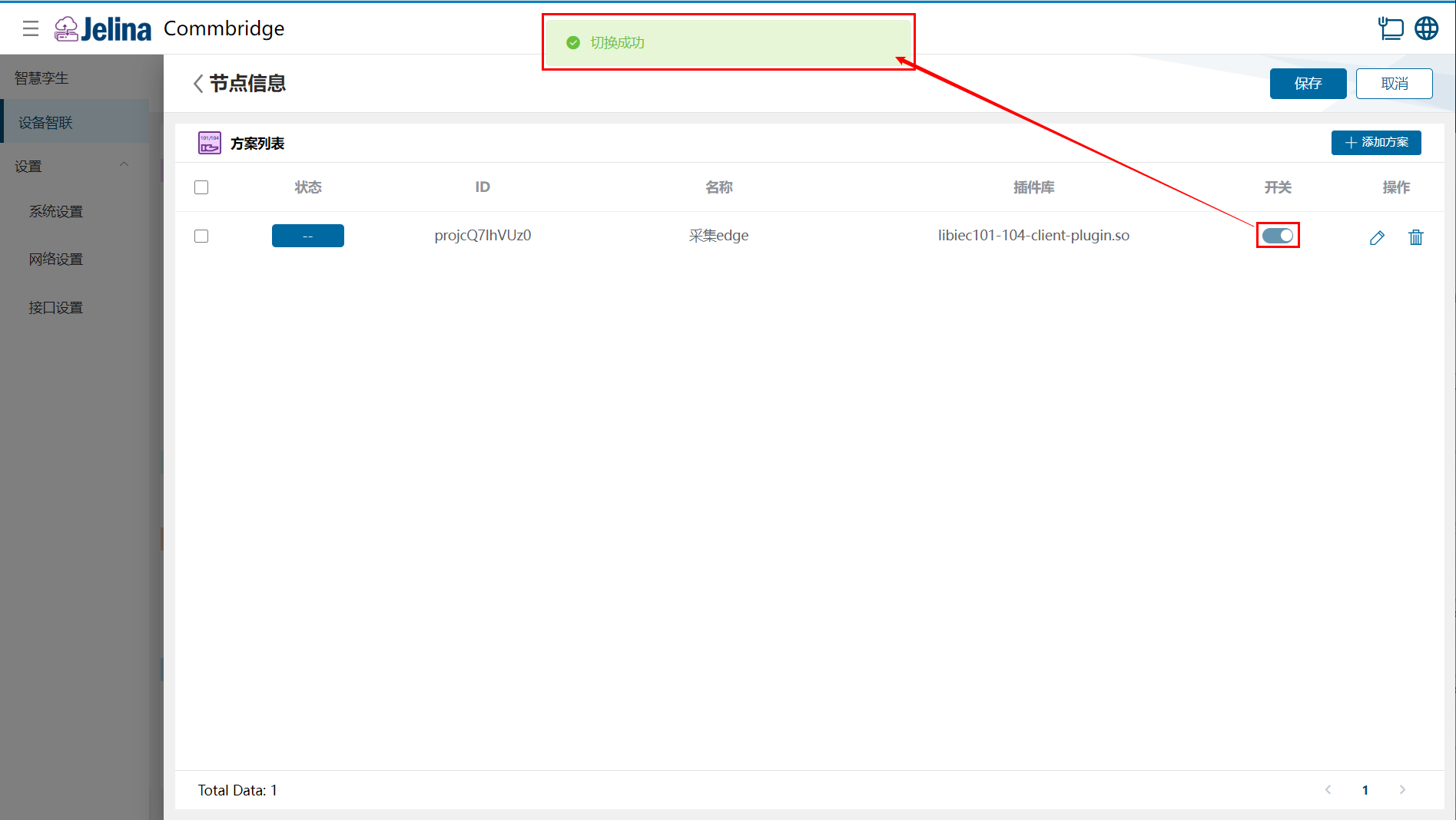
(6.) Enable the scheme, then click Save.
4. View results
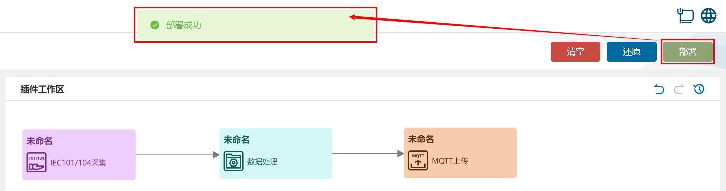
Section titled “4. View results”(1.) Click Deploy in Device Connectivity to deploy successfully.
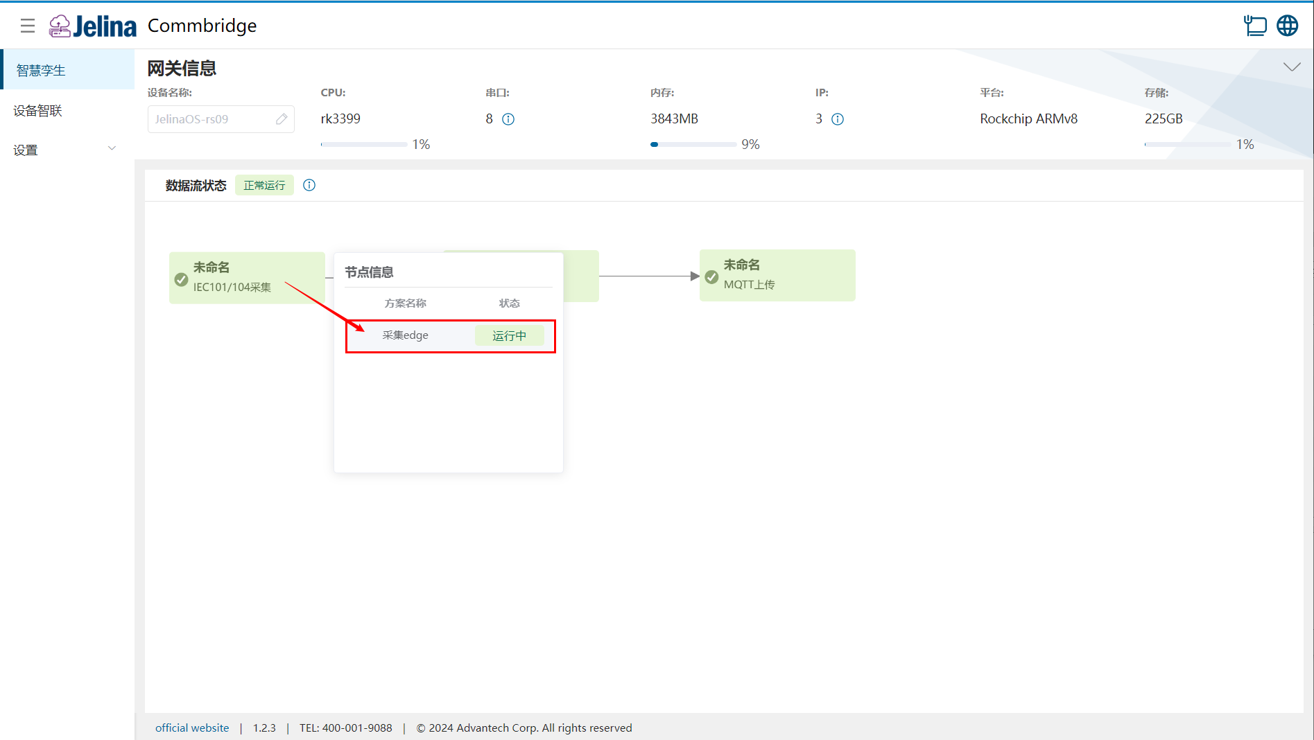
(2.) Switch to Digital Twin and hover over the IEC104 Acquisition node to display its information list.
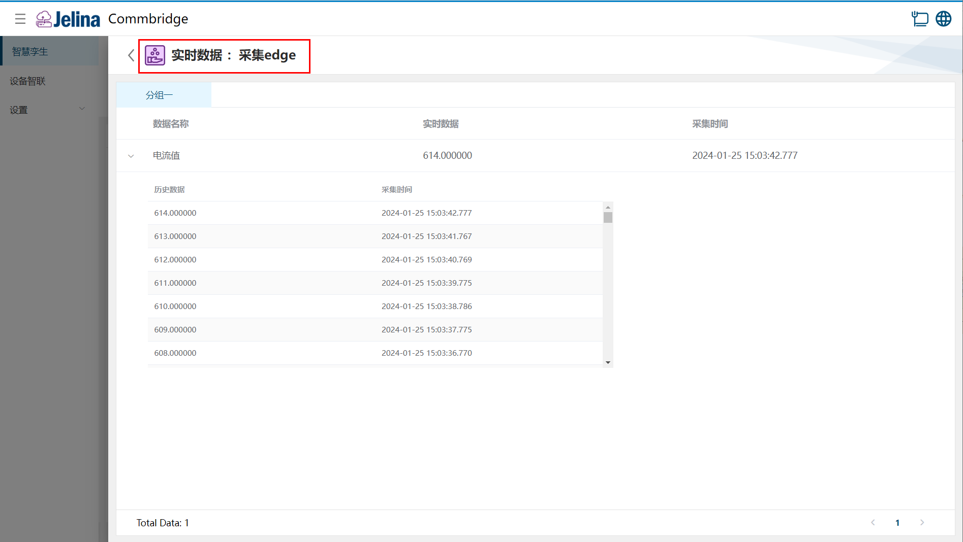
(3.) Click the scheme to view real-time and historical point data for its groups.
5. Configuration details
Section titled “5. Configuration details”Connection settings
Section titled “Connection settings”| Parameter | Description | Format | Example |
|---|---|---|---|
| Scheme name | User-defined name for the scheme | Nonempty | IEC 104 acquisition |
| Protocol | IEC 104 power-system protocol | Nonempty | IEC 104(TCP) |
| Cause of transmission size | Size of the cause of transmission (COT) in bytes; defaults to 1 byte | 1, 2 | 2 |
| Common address length | Size of the ASDU common address (CA) in bytes; defaults to 2 bytes (16 bits) | 1, 2 | 2 |
| Information object address length | Size of the information object address (IOA); defaults to 3 bytes (24 bits) | 1, 2, and 3 | 3 |
| Originator address | User-defined | Number, range: [0,255] | 0 |
| Application service data unit common address | Common address (CA) of the application service data unit (ASDU), set when issuing a general interrogation or sending a command | Number, range: [0,2147483647] | 1 |
| General interrogation interval | Interval for general interrogation in milliseconds; 0 disables periodic general interrogation | Number, range: [0,2147483647] | 0 |
| Host | IP address of the IEC 104 master (the device running the simulator, or controlled station) | Address in decimal notation | 192.168.220.146 |
| Port | IP port number of the IEC 104 master; enter the actual port, matching the simulator’s port | Number, range: [1, 65535] | 2404 |
| K | Send-window size: maximum number of sent but not yet acknowledged I-format APDUs | Number, range: [1,32767] | 12 |
| W | Maximum number of unacknowledged APDUs the receiver can accept | Number, range: [1,32767] | 8 |
| t0 | Connection establishment timeout. Attempts to reconnect if no connection is established | Number, range: [1,255] | 30 |
| t1 | APDU transmission or test timeout: time to wait for acknowledgment. Data must be retransmitted if acknowledgment is not received | Number, range: [1,255] | 15 |
| t2 | Acknowledgment timeout: time from the slave’s spontaneous data transmission to receipt of an S-format acknowledgment frame; if no data is sent within t2, the next acknowledgment frame should be sent |
Number, range: [1,255] | 10 |
| t3 | Heartbeat timeout: if no data is exchanged within t3, a U-format test frame should be sent to ensure continued link-layer activity | Number, range: [1,255] | 20 |
Note:
- K defaults to 12: at most 12 sent I-format APDUs may remain unacknowledged. Once this window limit is reached, the sender must wait for an acknowledgment before continuing to send I-format APDUs.
- W defaults to 8: after receiving 8 APDUs, the master must reply with an S-format acknowledgment. Applies to the master. In theory,
W < 2/3K.- Defaults: t0 = 30s, t1 = 15s, t2 = 10s, and t3 = 20s. In theory,
t2 < t1 < t3.- t0–t3 are in seconds.
Add a group
Section titled “Add a group”| Parameter | Description | Format | Example |
|---|---|---|---|
| Group name | User-defined name for the group | Nonempty | Group 1 |
| Group number | All data in this group belongs to the corresponding group. During general interrogation, the group number can select the relevant group data, using general interrogation values 001–20 | Seconds; number, range: [0,16] | 1 |
| Teleindication (DI) point offset | Offset for all teleindication (digital input DI) data; supports decimal and hexadecimal | Decimal range: [1,2147483647] Hexadecimal range: [0x0,0xffff] |
0x0 |
| Remote control (DO) point offset | Offset for all remote control (digital output DO) data; supports decimal and hexadecimal | Decimal range: [1,2147483647] Hexadecimal range: [0x0,0xffff] |
0x6001 |
| Telemetry (AI) point offset | Offset for all telemetry (analog input AI) data; supports decimal and hexadecimal | Decimal range: [1,2147483647] Hexadecimal range: [0x0,0xffff] |
0x3e9 |
| Remote adjustment (AO) point offset | Offset for all remote adjustment (analog output AO) data; supports decimal and hexadecimal | Decimal range: [1,2147483647] Hexadecimal range: [0x0,0xffff] |
0x6201 |
Add data
Section titled “Add data”| Parameter | Prerequisite | Description | Format | Example |
|---|---|---|---|---|
| Data alias | User-defined data name, matching the key to acquire | Nonempty | Data 1 | |
| Information object address | Information object address (InfoAdr), distinguishing applications such as teleindication and telemetry; each information item occupies a different address | Number; see below | 0 | |
| Data category | Teleindication is digital input DI; remote control is digital output DO; telemetry is analog input AI; remote adjustment is analog output AO | AI, DI | AI | |
| Data type | Data type of the point being acquired | Select from the drop-down list; see below | ||
| Initial value | Data type of the point being acquired | Select from the drop-down list; see below | ||
| Include timestamp | Whether to include a timestamp indicating when the information was sent | Yes, No; see below | No | |
| Timestamp type | Include timestamp is Yes | Timestamp type. IEC 104 does not support CP24Time2a | CP56Time2a, CP24Time2a | CP56Time2a |
| Read/write | Determined by the data category | Supports ro (read only) and wo (write only) | ro, wo; see below | No |
| Calculation | User-defined formula based on the data alias | Unrestricted |
Note:
Actual point address = teleindication/remote control/telemetry/remote adjustment point offset + information object address.
- The information object address range depends on its configured size: 1 byte gives [0-255]; 2 bytes gives [0-65535]; 3 bytes gives [0-16777215].
Data types:
- DI: Single Point Information or Double Point Information.
- DO: Single Command, Double Command, or Regulating Step Command.
- AI: Step Position Information, Bitstring32, Measured Value Normalized, Measured Value Scaled, Measured Value Short Floating, Integrated Total, or Measured Hormalized Without Quality.
- AO: BitString32 Command, Setpoint Command Normalized, Setpoint Command Scaled, or Setpoint Command Short Floating.
Read/write:
- ro: DI and AI default to ro (read only).
- wo: DO and AO default to wo (write only).