
GPIO Console
The GPIO plugin monitors changes in GPIO or upstream data and triggers writes to GPIO or downstream data. It changes I/O levels based on point conditions and writes point values when input levels change.
Note: A point can be a data point within an acquisition scheme or a GPIO.
-
Input control: after reading GPIO, send a custom value to a specified point according to the pull-low/pull-high trigger condition.
-
Output monitoring: monitor point changes and drive a specified GPIO high or low when conditions are met.
1. Create nodes
Section titled “1. Create nodes”(1) Open CommBridge Digital Twin, then switch to Device Connectivity on the left.
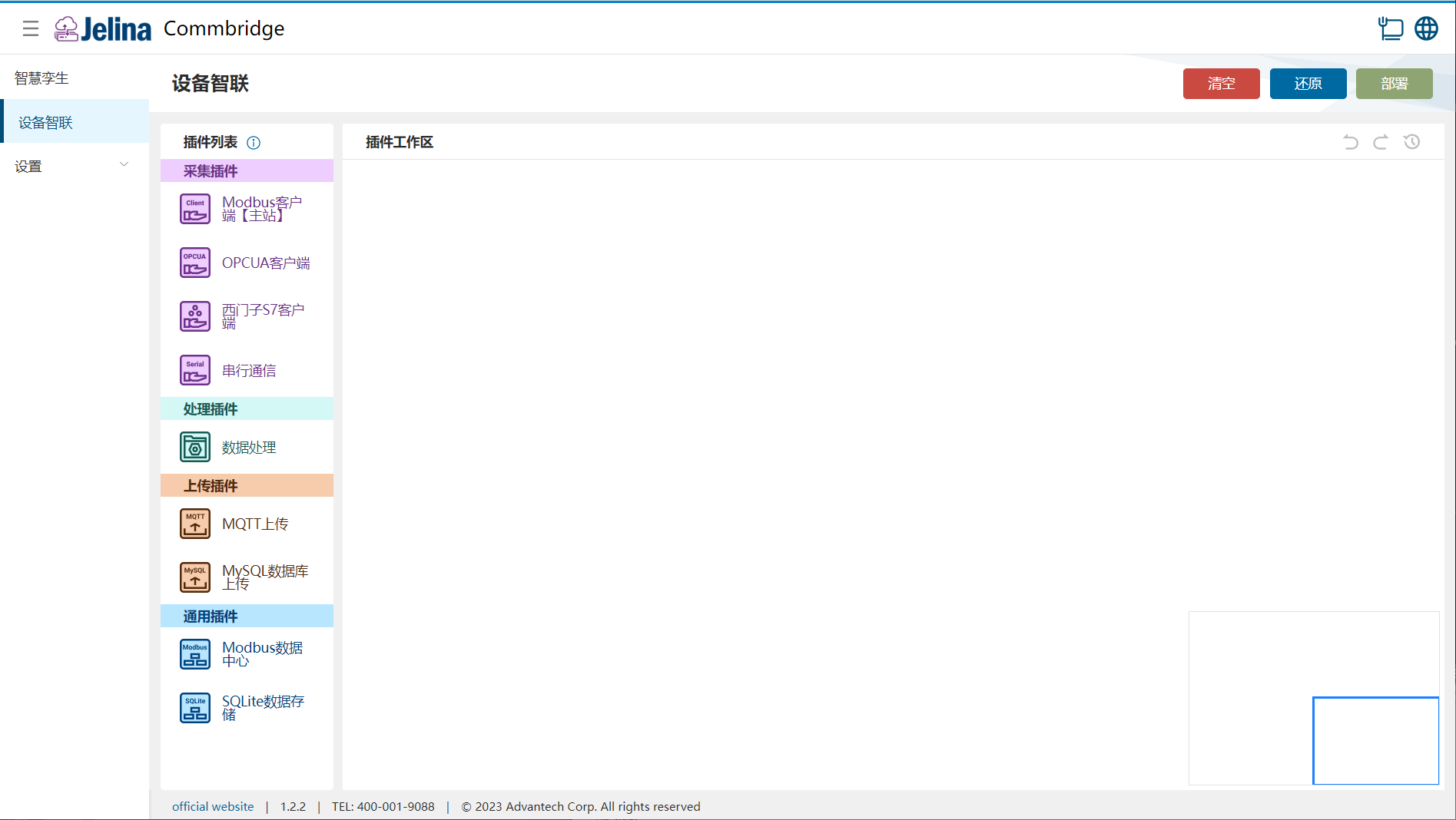
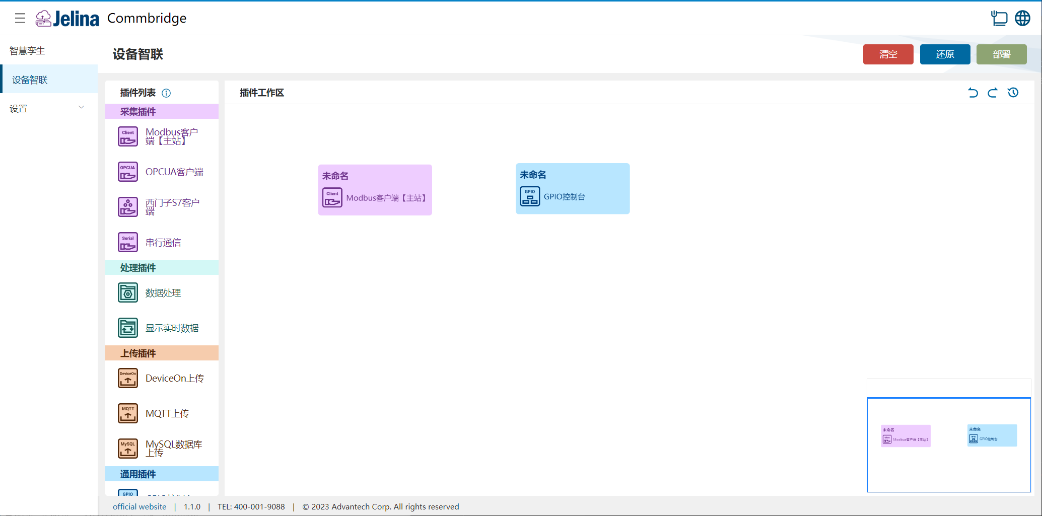
(2) Drag Modbus Client (Master) and GPIO Console into the workspace to create two nodes.
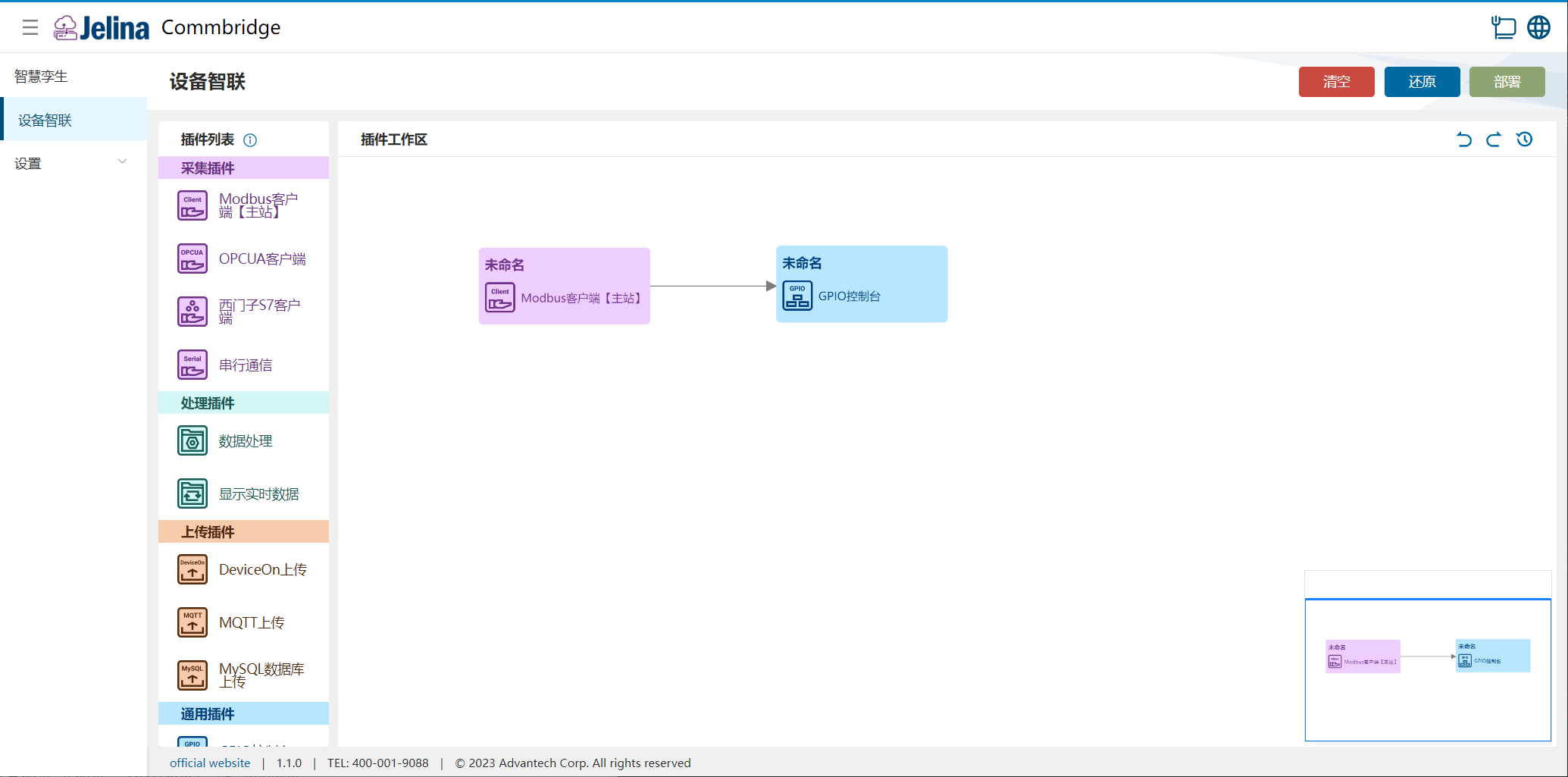
(3) Connect the nodes in order: Modbus Client (Master) → GPIO Console.
2. Create a scheme
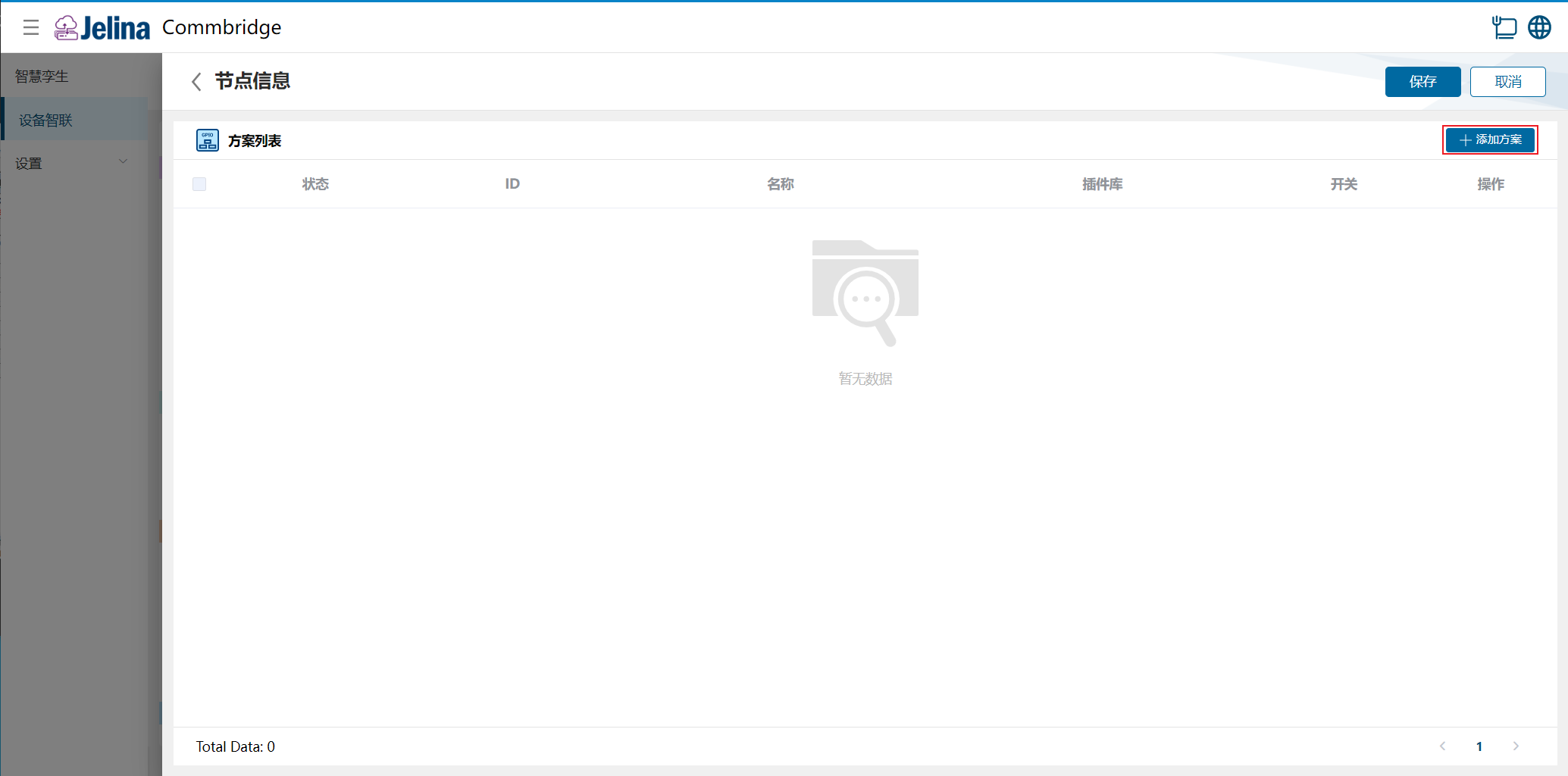
Section titled “2. Create a scheme”(1) Double-click GPIO Console and select Add scheme.
(2) Enter connection settings and select Next.
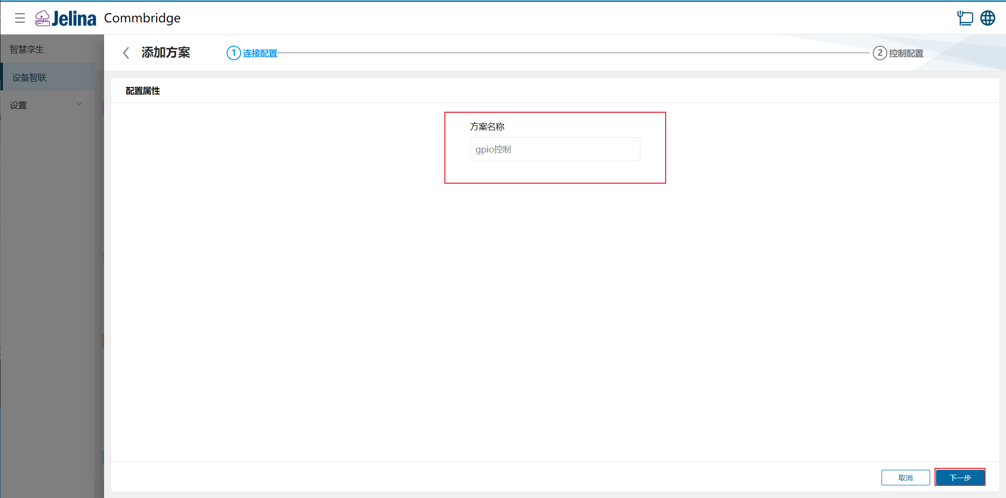
(3) Under Output monitoring, select Add data and configure it.
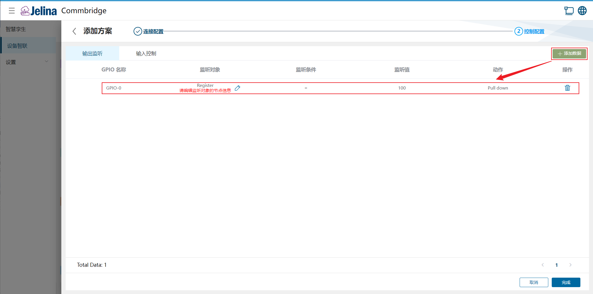
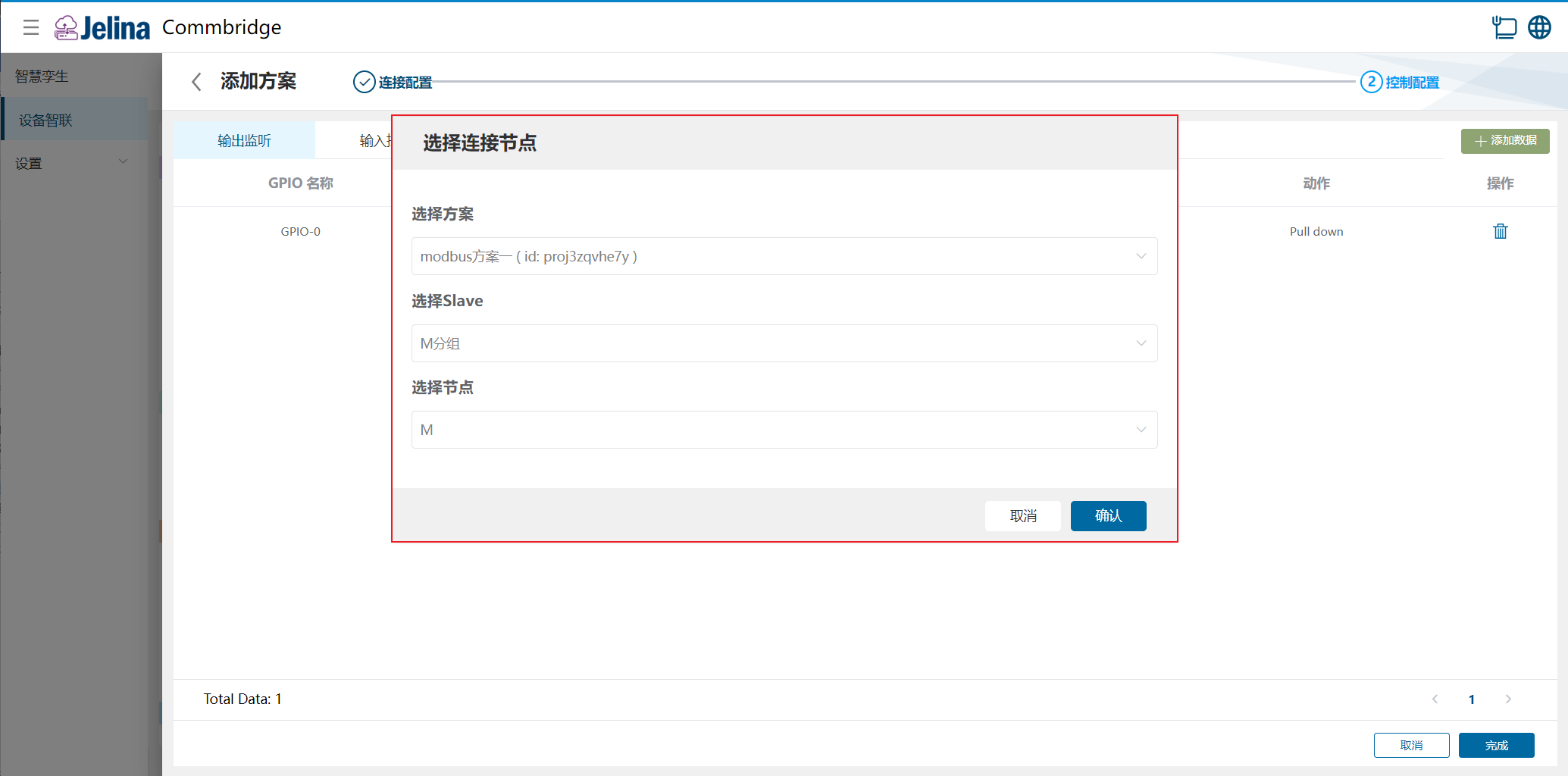
(4) Select Edit beside Register and choose a scheme.
(5) Under Output monitoring, select Add data and configure it.
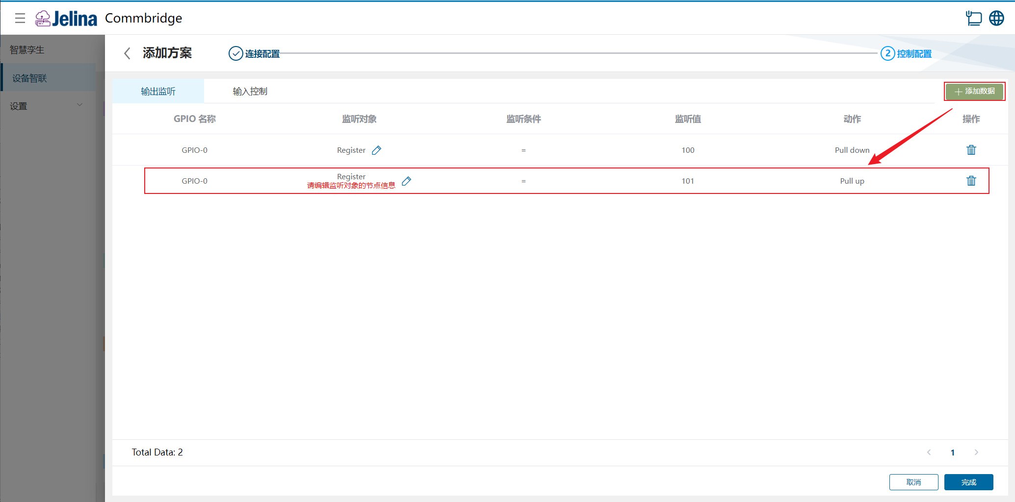
(6) Select Edit beside Register, choose a scheme, and confirm.
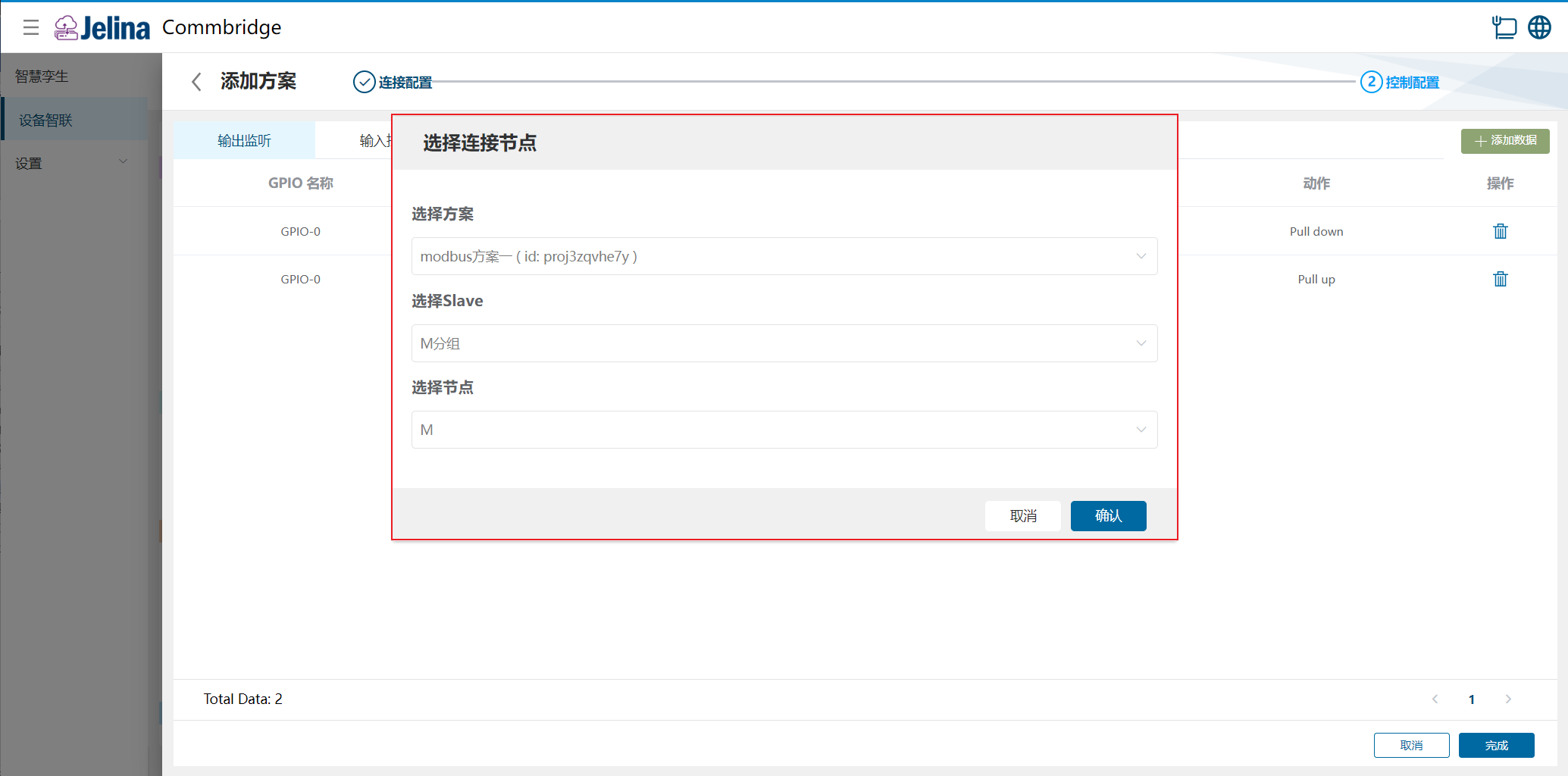
(7) Select Finish to add the acquisition scheme.
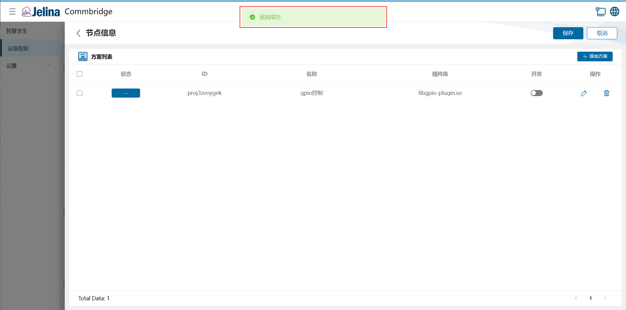
(8) Enable the scheme and select Save.
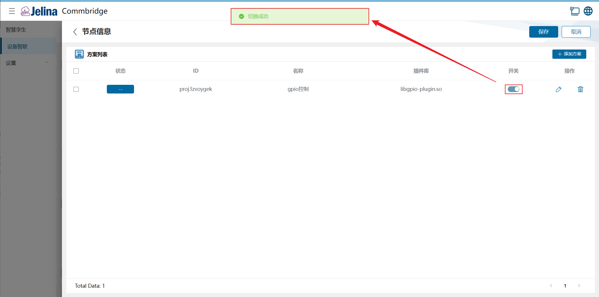
3. View results
Section titled “3. View results”(1) Select Deploy under Device Connectivity and wait for success.
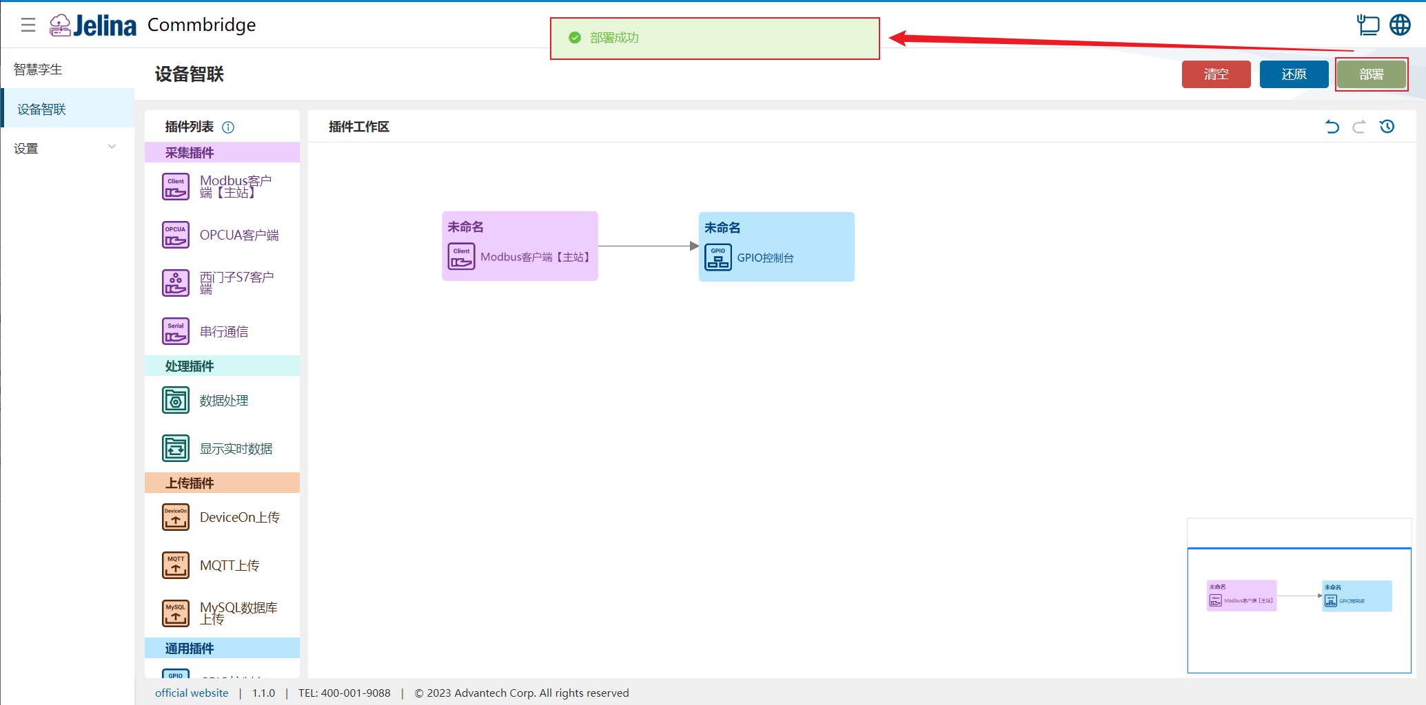
(2) Switch to Digital Twin and hover over Modbus Data Center to show node information.
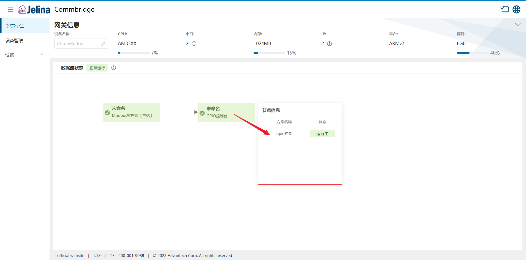
(3) Inspect the device’s GPIO states.


4. Configuration reference
Section titled “4. Configuration reference”Connection settings
Section titled “Connection settings”| Parameter | Description | Format | Example |
|---|---|---|---|
| Scheme name | User-defined scheme name | Nonempty | GPIO control |
Output monitoring
Section titled “Output monitoring”| Parameter | Description | Format | Example |
|---|---|---|---|
| GPIO name | Device GPIO pin, determined by physical hardware | Dropdown | GPIO-0 |
| Monitored target | Device GPIO or a point in an upstream acquisition scheme | GPIO or Register | Register |
| Condition | Greater than, less than, equal, greater than or equal, less than or equal, or not equal | Dropdown | = |
| Monitored value | Target comparison value | Number | 100 |
| Action | Action performed on the GPIO pin | Pull down or Pull up | Pull down |
- For GPIO targets, select Edit and choose the pin. Only equal and not-equal conditions are supported.
- For Register targets, select a scheme from an upstream acquisition plugin.
Input control
Section titled “Input control”| Parameter | Description | Format | Example |
|---|---|---|---|
| GPIO name | Device GPIO pin, determined by physical hardware | Nonempty | GPIO-1 |
| Controlled target | Device GPIO or a point in a downstream acquisition scheme | GPIO or Register | Register |
| Trigger condition | GPIO pin action | Pull down or Pull up | Pull up |
| Control value | Value to set on the controlled target | Dropdown | 101 |
- For GPIO targets, select Edit and choose the pin.
- For Register targets, select a scheme from a downstream acquisition plugin.
- Output monitoring and input control cannot use the same GPIO name.