
Siemens S7 acquisition
1. Create nodes
Section titled “1. Create nodes”(1.) Open CommBridge Digital Twin and switch to Device Connectivity.

(2.) Drag Siemens S7 Client, Data Processing, and MQTT Upload into the workspace to create three nodes.
(3.) Connect Siemens S7 Client → Data Processing → MQTT Upload.

2. Create a scheme
Section titled “2. Create a scheme”(1.) Double-click Siemens S7 Client and select Add scheme.
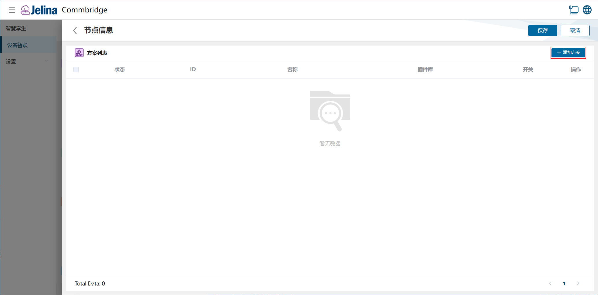
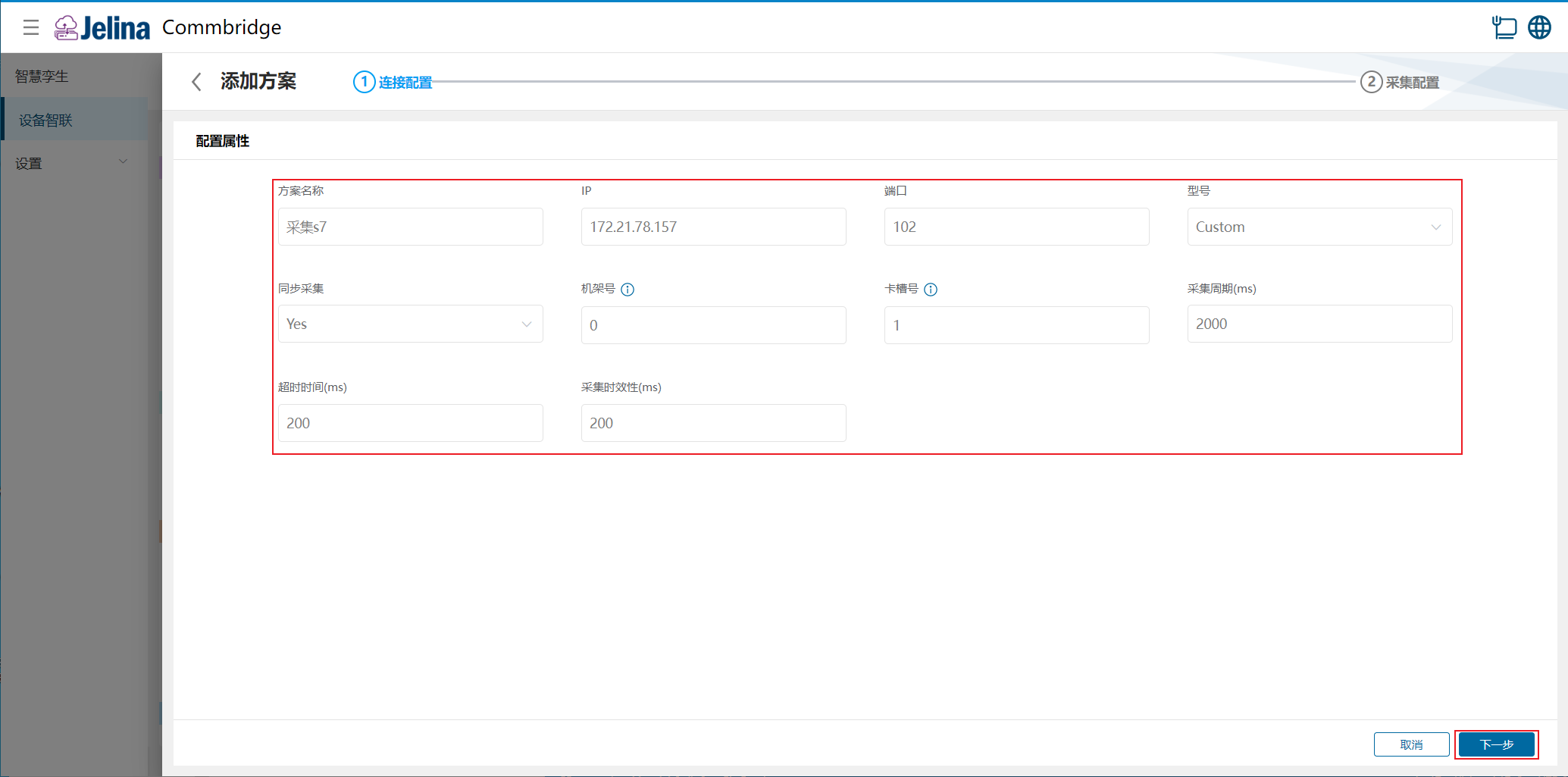
(2.) Enter connection settings and select Next.
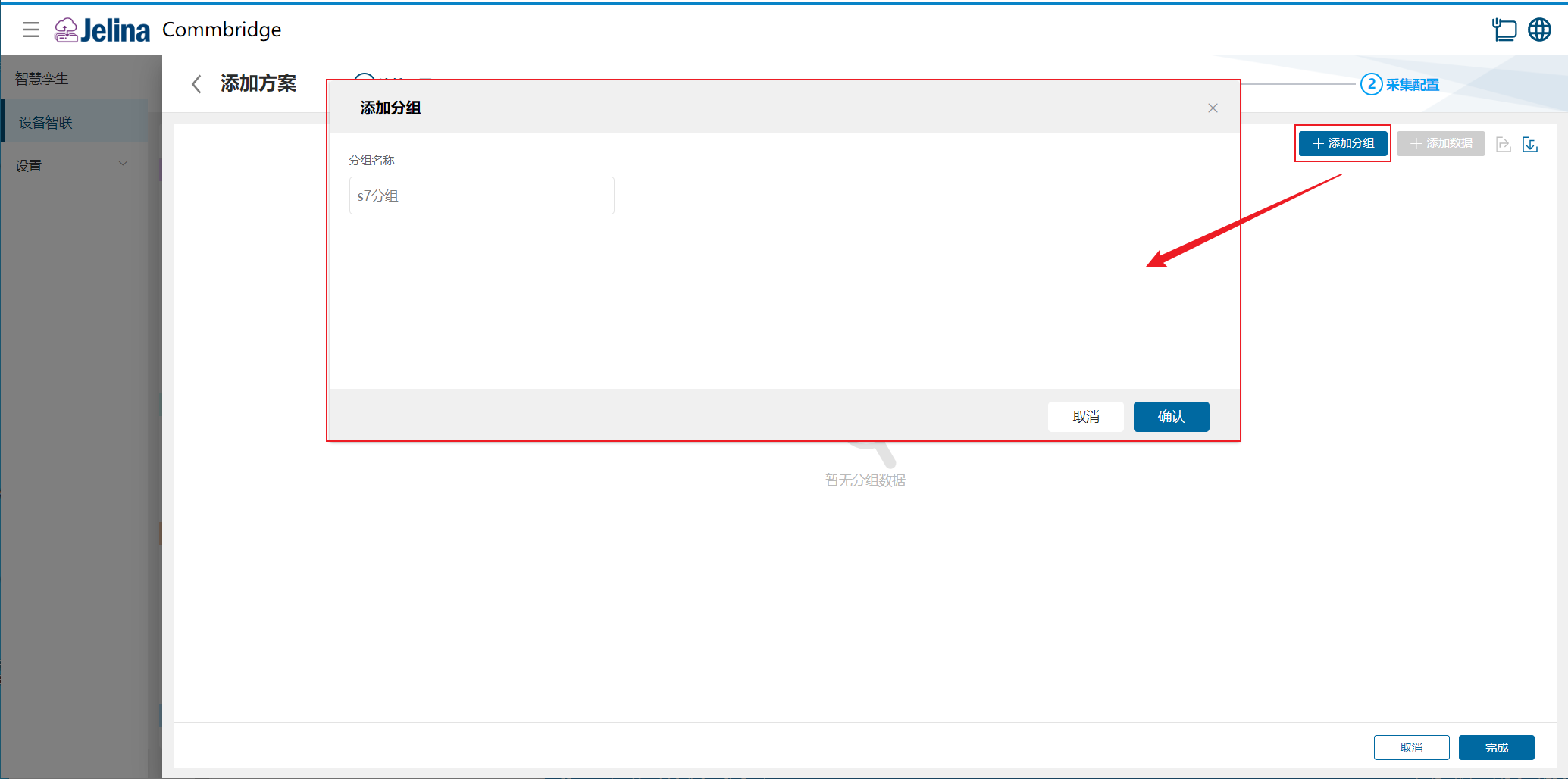
(3.) Select Add group, enter group information, and confirm.
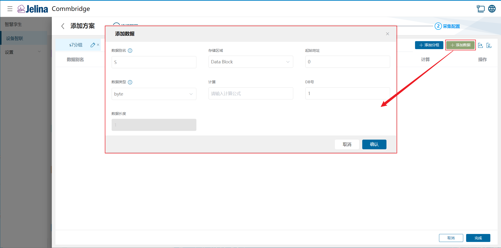
(4.) Select Add data, enter point configuration, and confirm.
(5.) Select Finish to add the acquisition scheme.
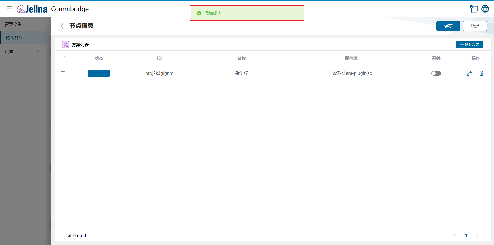
(6.) Enable the scheme and select Save.
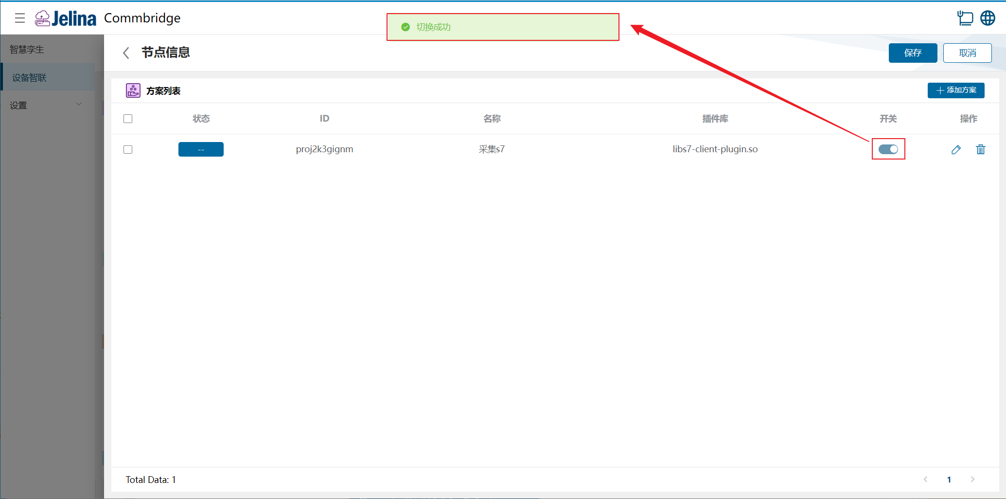
3. View results
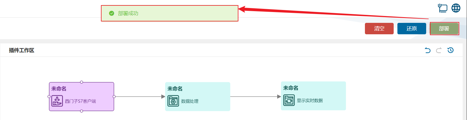
Section titled “3. View results”(1.) Select Deploy under Device Connectivity and wait for success.
(2.) Switch to Digital Twin and hover over Siemens S7 Client to display node information.
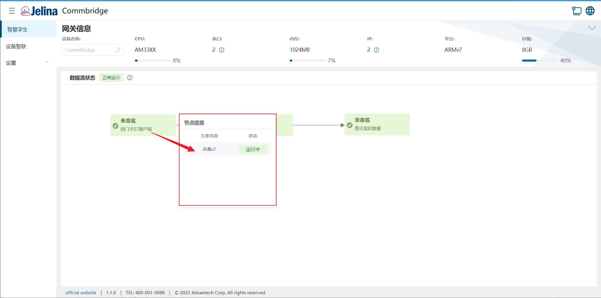
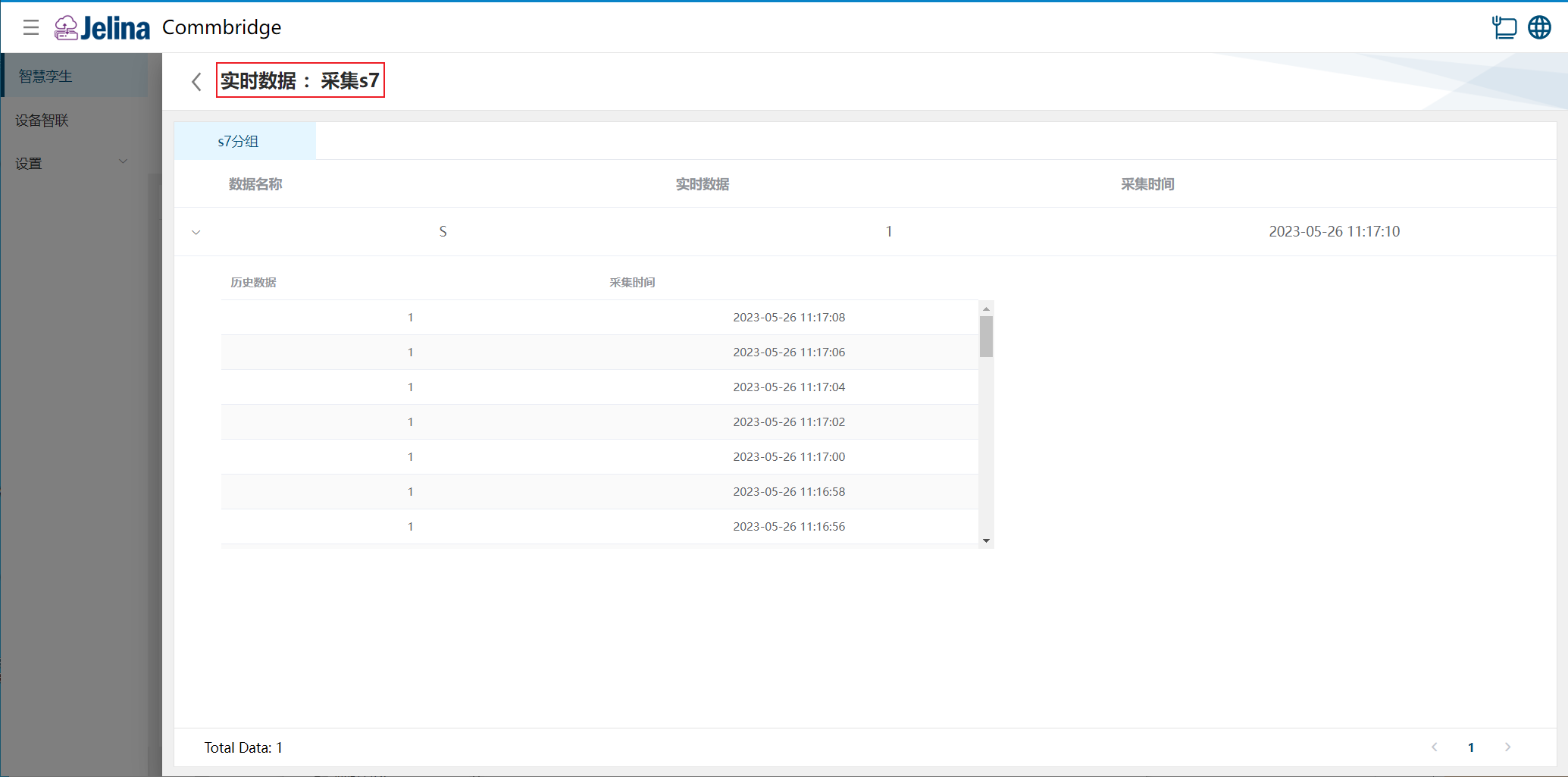
(3.) Select a scheme to view real-time and historical point data in its groups.
Real-time values are decimal.
4. Configuration reference
Section titled “4. Configuration reference”Connection settings
Section titled “Connection settings”| Parameter | Prerequisite | Description | Format | Example |
|---|---|---|---|---|
| Scheme name | User-defined scheme name | Nonempty | S7 acquisition | |
| IP | Source Siemens PLC IP address | Dotted-decimal address | 172.21.78.157 | |
| Port | Source Siemens PLC port | Integer, 1–65535 | 102 | |
| Model | Siemens S7 device model | Dropdown | Custom | |
| Rack | Rack containing the CPU | Number, 0–7 | 0 | |
| Slot | Slot containing the CPU | Number, 0–31 | 1 | |
| Synchronous acquisition | Whether acquisition is synchronous | Yes, No | Yes | |
| Acquisition interval | Synchronous acquisition is Yes | Polling interval in ms | Number, (100,2147483647] | 2000 |
| Data freshness | Synchronous acquisition is Yes | Time in ms | Number, (0, acquisition interval] | 1000 |
Note:
- Models: S7-300, S7-400, S7-1200, S7-1500, 200Smart, Custom. Select Custom if rack or slot numbers have been changed.
- Siemens S7 PLCs have one main rack and several expansion racks. The CPU rack is the main rack, numbered 0; expansion racks are numbered 1, 2, 3, and so on.
- Slots assign positions to CPU, power supply, interface, I/O signal, communication, and function modules. Each module occupies one slot.
- With synchronous acquisition set to Yes, groups share acquisition interval, timeout, and freshness settings. With No, each group configures them independently.
Explanation:
-
In common S7 client connections, the remote TSAP uses two bytes: the first represents the connection type, and the second encodes the CPU rack and slot numbers. Specific TSAP settings must match the PLC connection configuration.
-
Local TSAP corresponds to the acquisition application’s address; Remote TSAP corresponds to the PLC address. Rack and slot values vary by PLC model.
Rack/Slot settings for Siemens S7 PLCs:
| PLC model | Rack | Slot |
|---|---|---|
| S-300 | 0 | 2 |
| S-400 | 0 | 2 |
| S-1200 | 0 | 0 or 1 |
| S-1500 | 0 | 0 or 1 |
| S-300Smart | 0 | 2 |
Add groups
Section titled “Add groups”| Parameter | Prerequisite | Description | Format | Example |
|---|---|---|---|---|
| Group name | User-defined group name | Nonempty | S7 group | |
| Acquisition interval | Synchronous acquisition is No | Polling interval in ms | Number, (100,2147483647] | 2000 |
| Data freshness | Synchronous acquisition is No | Time in ms | Number, (0, acquisition interval] | 1000 |
Note:
- S7 can read only 20 data items at a time.
- Acquisition interval and freshness apply to all points in the group.
Add data
Section titled “Add data”| Parameter | Prerequisite | Description | Format | Example |
|---|---|---|---|---|
| Data alias | Data name, unique within the group | Nonempty; cannot begin with a digit or underscore or contain spaces | S | |
| Memory area | Data storage location | Data Block | Data Block | |
| DB number | Memory area is Data Block | Register address offset | Number, [0,2147483647] | 1 |
| Start address | Zero-based register address matching the device | Number, [0,2147483647] | 0 | |
| Data type | Determined by register type | bit, byte, short, ushort, int, unit, long, ulong, float, double, string | byte | |
| Bit offset | Data type is bit | Offset starting from the low byte | Number, [0,7] | 1 |
| Data length | Data type is string | Length to acquire | 1, 2 | 1 |
| Byte order | Determined by register and data types | Memory order for multibyte types | Big Endian, Little Endian | Big Endian |
| Calculation | Compute acquired data |
Note: Merker, Input, Output, Counter, and Timer memory areas are not yet available.
5. Siemens S7 protocol parameter details
Section titled “5. Siemens S7 protocol parameter details”Memory areas:
| Abbreviation | Area | Code | Description |
|---|---|---|---|
| [M] | Merker | 0x83 | Marker variables and flag registers |
| [DB] | Data Block | 0x84 | Common storage for data required by device functions; block numbers form part of addresses |
| [I] | Input | 0x81 | Digital and analog input module values mapped into memory |
| [Q] | Output | 0x82 | Corresponding memory-mapped outputs |
| [C] | Counter | 0x1c | [C] values of counters used by the PLC program |
| [T] | Timer | 0x1d | [T] values of counters used by the PLC program |
Data types:
| Type | Description |
|---|---|
| bit | Boolean, length 1, range 0–1 |
| byte | Byte, length 8, range 0–255 |
| short | Two-byte signed integer |
| ushort | Two-byte unsigned integer |
| int | Four-byte signed integer |
| unit | Four-byte unsigned integer |
| long | Eight-byte signed integer |
| ulong | Eight-byte unsigned integer |
| float | Four-byte single-precision floating-point value |
| double | Eight-byte double-precision floating-point value |
| string | Eight-byte string |
One byte is 8 bits.
Example:
- To acquire the second bit of the third byte in DB block 123, select Data Block, enter DB number 123, and choose Byte as the data type.
- Example address DB123X 2.1 accesses the second bit of the third byte in data block #123.