
GPIO Read/Write
1. Create nodes
Section titled “1. Create nodes”(1) Open CommBridge Digital Twin and switch to Device Connectivity.
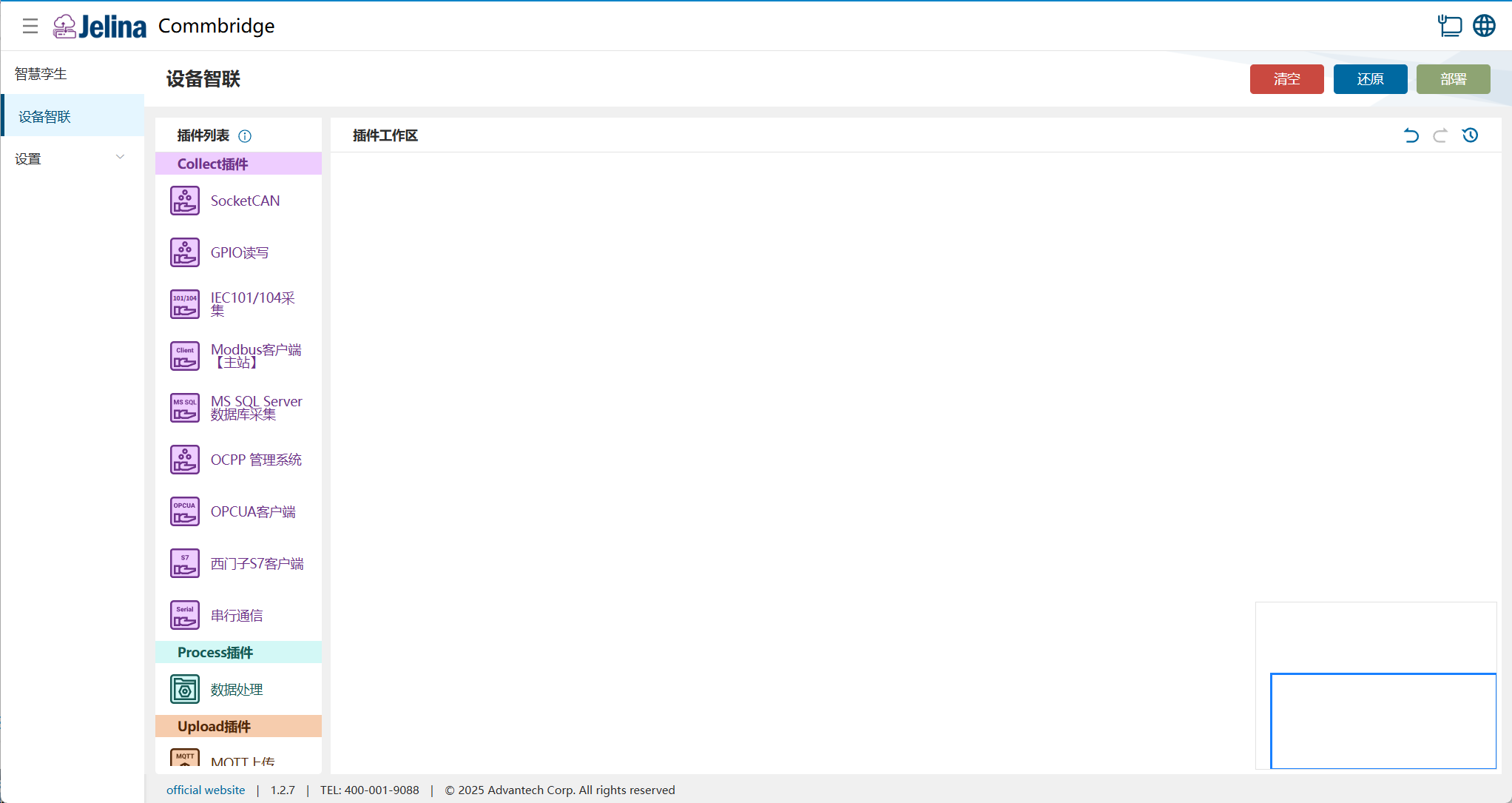
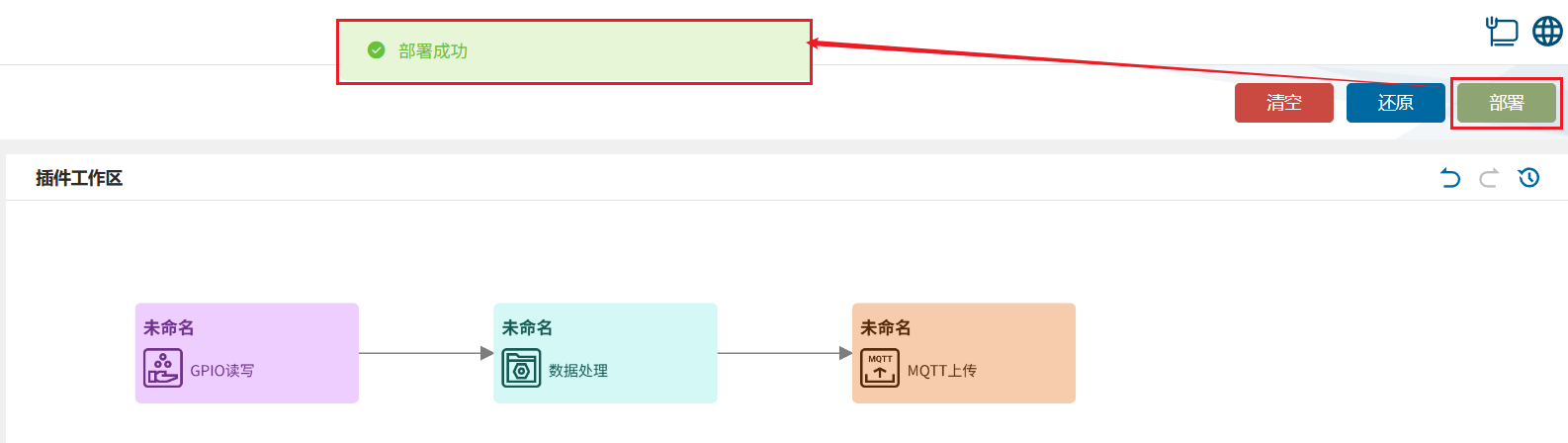
(2) Drag GPIO Read/Write, Data Processing, and MQTT Upload into the workspace to create three nodes.

(3) Connect GPIO Read/Write → Data Processing → MQTT Upload.

2. Create a scheme
Section titled “2. Create a scheme”(1) Double-click GPIO Read/Write and select Add scheme.
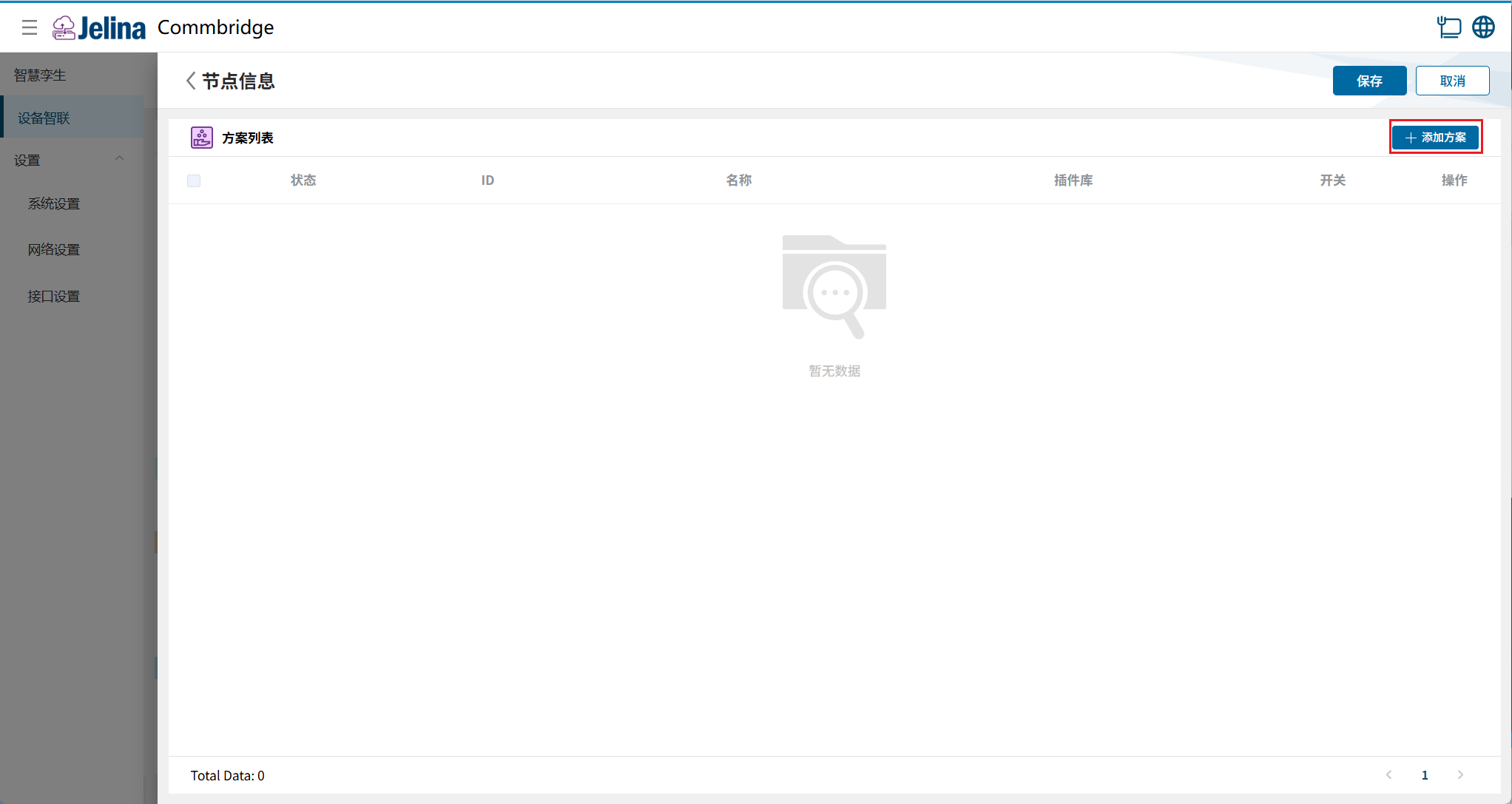
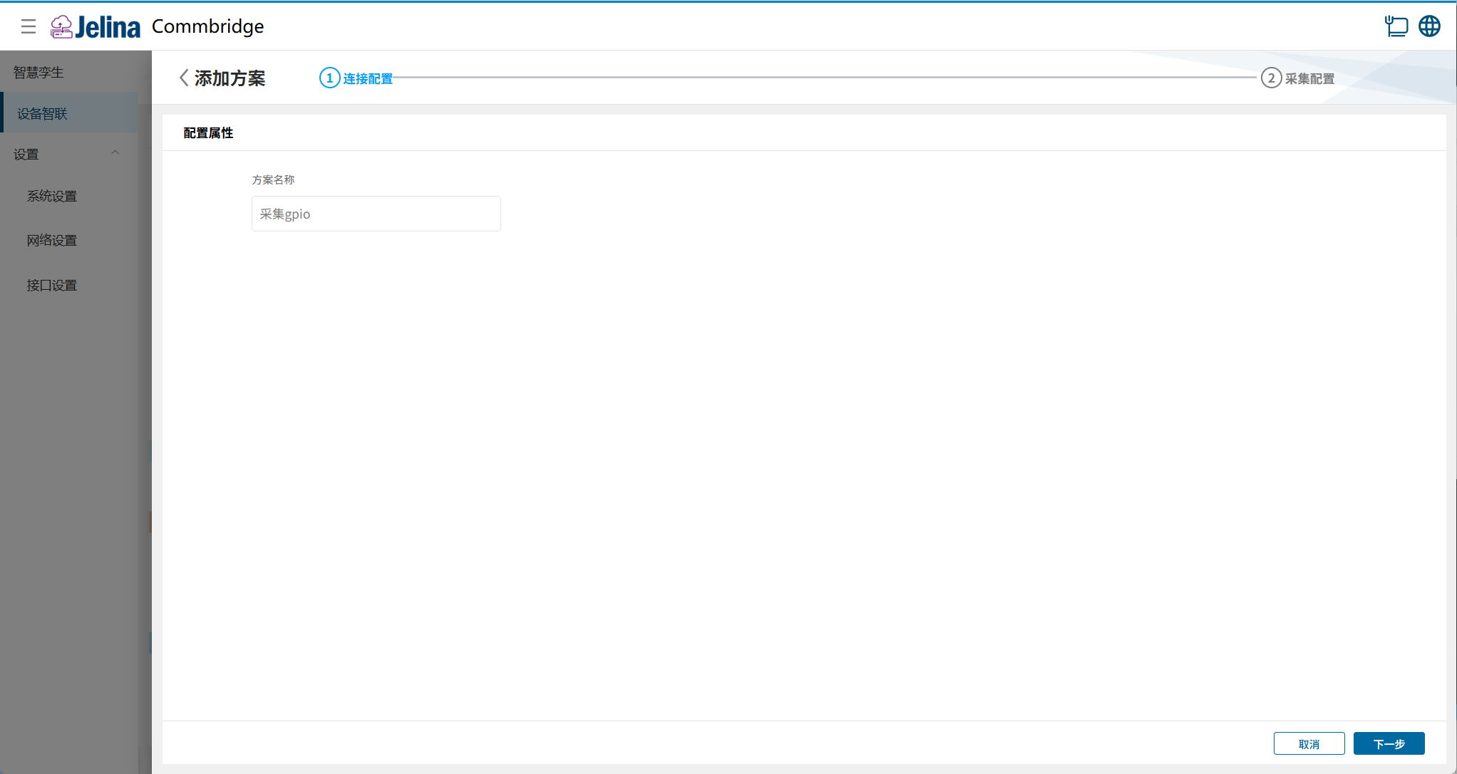
(2) Enter connection settings and select Next.
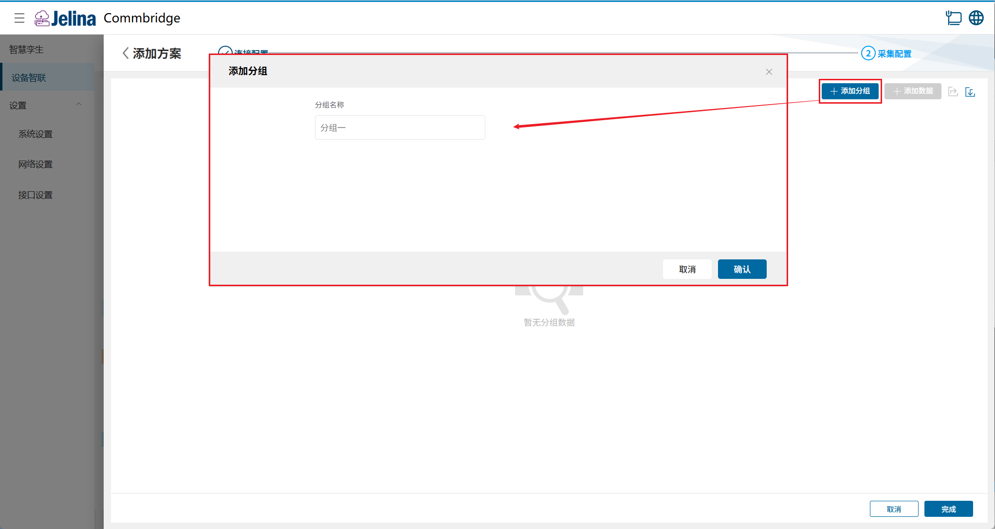
(3) Select Add group, enter group information, and confirm.
(4) Select Add data, enter point configuration, and confirm.
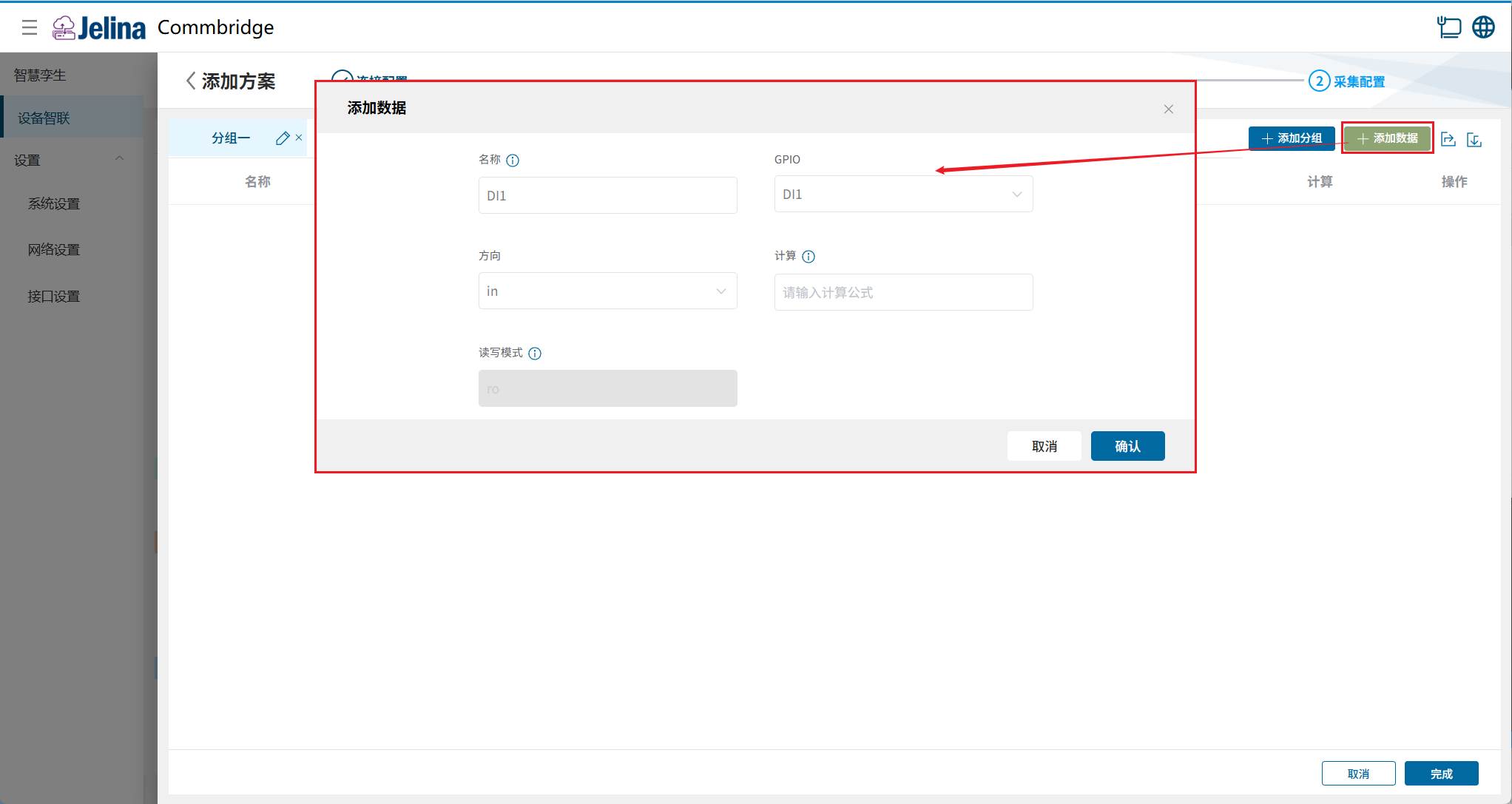
(5) Select Finish to add the acquisition scheme.
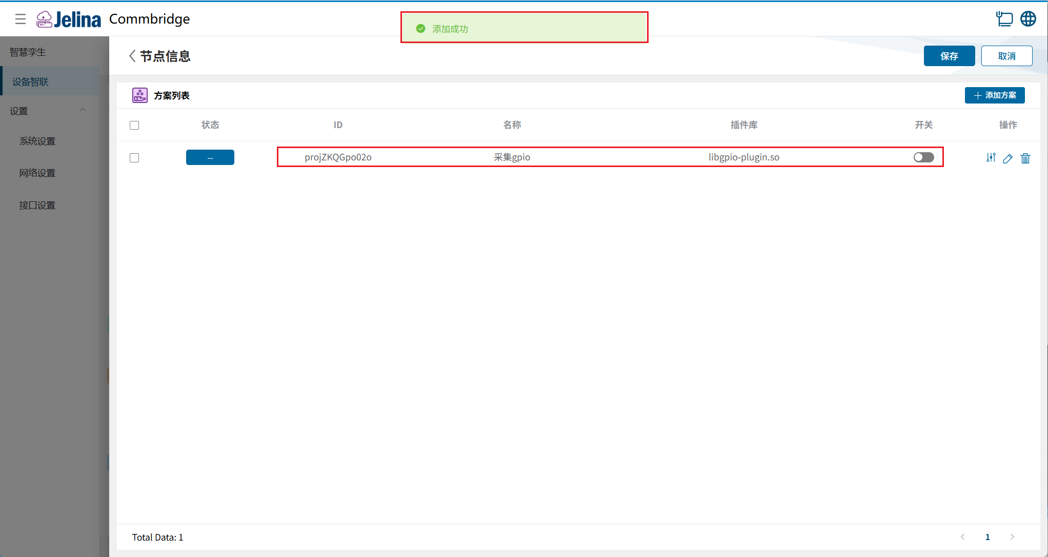
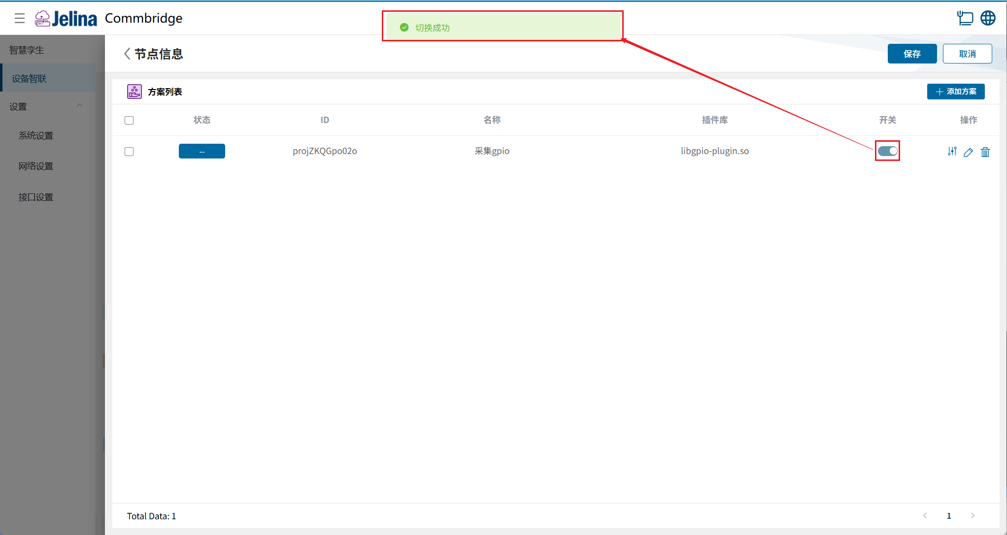
(6) Enable the scheme and select Save.
3. View results
Section titled “3. View results”(1) Select Deploy under Device Connectivity and wait for success.
(2) Switch to Digital Twin and hover over GPIO Read/Write to display node information.
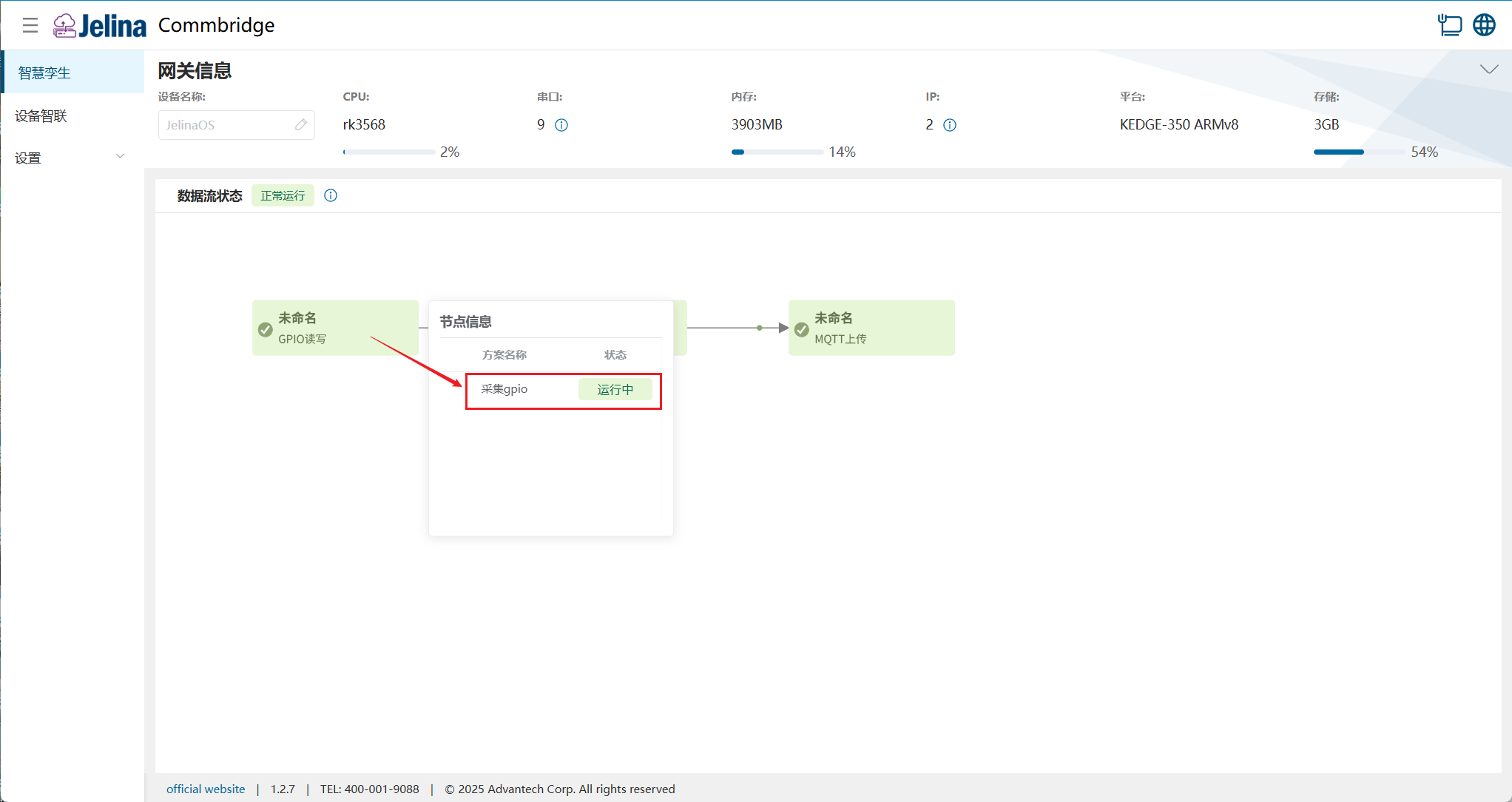
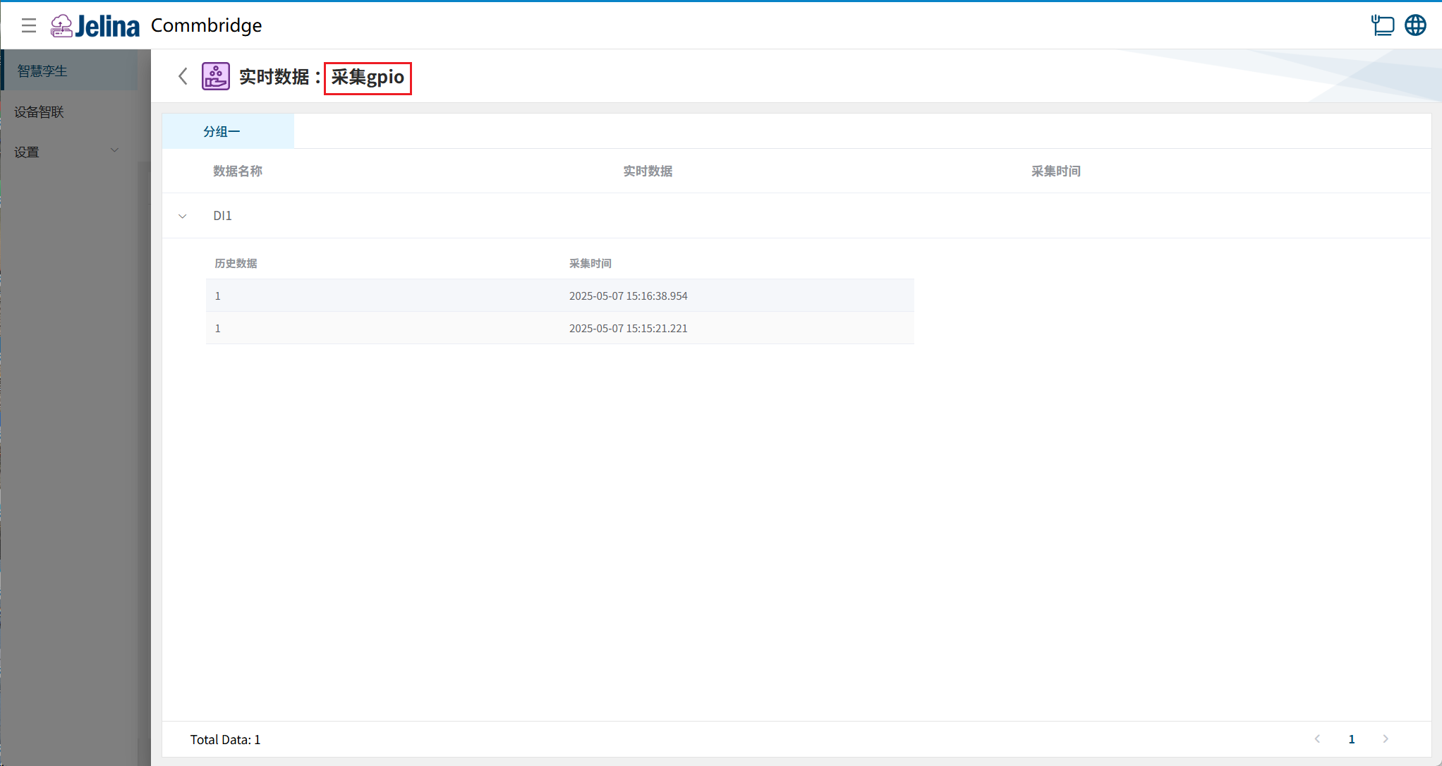
(3) Select a scheme to view real-time and historical point data for its groups.
Acquired data before processing:
4. Configuration reference
Section titled “4. Configuration reference”Connection settings
Section titled “Connection settings”| Name | Description | Format | Example | Notes |
|---|---|---|---|---|
| Scheme name | User-defined scheme name | Nonempty | GPIO acquisition |
Add groups
Section titled “Add groups”| Parameter | Description | Format | Example | Notes |
|---|---|---|---|---|
| Group name | User-defined group name | Nonempty | GPIO group |
Add data
Section titled “Add data”| Parameter | Description | Format | Example | Notes |
|---|---|---|---|---|
| Name | Point name, unique within a group | Nonempty; cannot begin with a digit or underscore or contain spaces | DI1 | |
| GPIO | Physical device GPIO pin with a unique identifier, such as GPIO1 or GPIO2 | Dropdown | DI1 | |
| Direction | Input/output mode: in reads external signals; out controls external devices | Dropdown | in | |
| Read/write mode | Supports ro (read-only) and rw (read/write) | ro, rw, wo | ro | |
| Calculation | User-defined formula based on data aliases | Unrestricted |
Note:
Supported GPIO mappings:
- EPC-5710: GPIO1–GPIO5.
- Kedge-350: DI1–DI8 and DO1–DO8.